Disk-type permanent magnetic speed regulator

A permanent magnet governor, disk type technology, applied in the direction of electrical components, electromechanical devices, etc., can solve the problems of electromagnetic interference, many fault points, short life cycle, etc., to reduce mechanical friction and wear, and accurately control the size of the air gap , The effect of improving the stress situation

Inactive Publication Date: 2014-09-17
QINGDAO SPRING ENERGY TECH
View PDF7 Cites 9 Cited by
  • Summary
  • Abstract
  • Description
  • Claims
  • Application Information

AI Technical Summary

Problems solved by technology

Dampers and valves are traditional methods, which can effectively adjust the flow or pressure, but the disadvantages are also obvious: no energy saving, easy to cause impact in the system, and loud noise
Although the hydraulic governor can adjust the speed and save energy to a certain extent, its efficiency is low and it is not stable enough
Inverter and internal feedback chopper speed regulation use the method of directly changing the motor speed to adjust the system and load. The efficiency is high and the energy saving effect is good. Short, with electromagnetic interference, high maintenance costs
In 1

Method used


Image

  • Disk-type permanent magnetic speed regulator
  • Disk-type permanent magnetic speed regulator
  • Disk-type permanent magnetic speed regulator

Examples


Embodiment 1

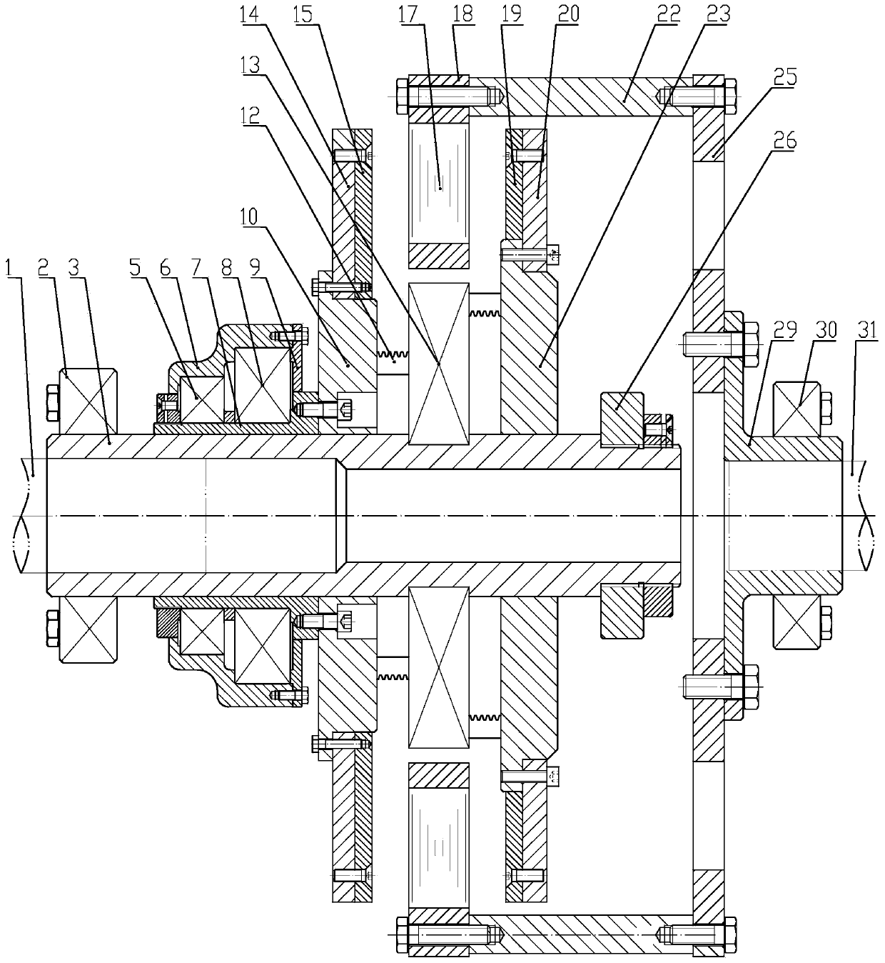
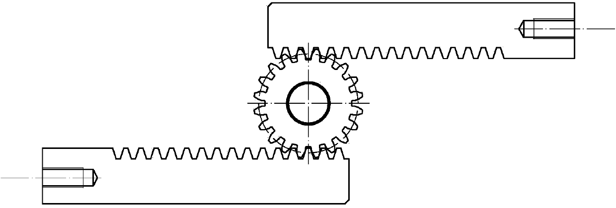
[0028] see Figure 1-Figure 5 , the disc-type permanent magnet governor of the present invention includes split and coaxial first shaft 1 and second shaft, the first shaft 1 is sleeved in the first shaft sleeve 3, and the first shaft sleeve 3 is externally sleeved for adjustment Speed ​​mechanism, slider Ⅰ, support frame, slider Ⅱ and limit plate, the speed regulating mechanism is connected with slider Ⅰ through bolts, the support frame is installed between slider Ⅰ and slider Ⅱ, and the support frame is connected through a rack and pinion mechanism Connect slider Ⅰ and slider Ⅱ; slider Ⅰ connects conductor plate Ⅰ and steel plate Ⅰ through bolts, and slider Ⅱ connects conductor plate Ⅱ and steel plate Ⅱ through bolts; the limit plate is installed on the first shaft sleeve 3 far from the first one end of axis 1;

[0029] The second shaft is socketed in the second shaft sleeve, and the load connection plate is installed on the second shaft sleeve. A connecting rod is installed...

Embodiment 2

[0040] see Figure 5 and Figure 6 , the speed regulating mechanism on the first shaft sleeve 3 of the disc permanent magnet speed governor of the present invention can be a chute structure, including bearing I5, bearing II8, inner casing 35, outer casing 38, sliding sleeve 7, bearing pressure Cover I36, bearing gland II39; the inner shell 35 is symmetrically opened with two helical sliding grooves in the same direction on the outer cylindrical surface, and the inverted groove shaft 33 and the inverted groove sliding sleeve 32 are nested and installed in the sliding grooves of the inner casing 35 , the outer shell 38 and the inner shell 35 are nested and assembled, and are connected by two pairs of inverted groove shafts 33 and inverted groove sliding sleeves 32; the bearing I5 is placed in the inner shell 35, and the outer ring of the bearing I5 is fixed by the bearing gland I36 , the inner ring of bearing I5 is fixed by lock nut I34; bearing II8 is placed in the outer shell...


PUM


Abstract

The invention discloses a disk-type permanent magnetic speed regulator. The disk-type permanent magnetic speed regulator comprises a first shaft and a second shaft which are coaxially arranged in a split mode. The end of the first shaft is connected with sliding blocks and conductor disks through a speed regulation mechanism. The conductor disks are made of materials with good conductivity. The end of the second shaft is connected with a permanent magnetic rotary disk through a load connecting disk. Permanent magnets are mounted on the permanent magnetic rotary disk and are arranged between the conductor disks. According to the disk-type permanent magnetic speed regulator, the structure of a permanent magnetic rotor is simplified, and the disk-type permanent magnetic speed regulator is only provided with one permanent magnetic rotary disk, so that the weight of the permanent magnetic rotor is greatly reduced on the basis of achieving air gap regulation, and the permanent magnetic rotor is more stable in the rotating process; consequently, mechanical friction and mechanical abrasion are reduced, interference of vibration is avoided, loss of transmission components is reduced, vibration is isolated, and noise is lowered; meanwhile, the disk-type permanent magnetic speed regulator is easy to install and debug, free of precise centering, capable of allowing a certain axial movement, and capable of changing output rotating speed and achieving the purposes of speed regulation and energy conservation through the design of two kinds of speed regulation mechanisms, and the size of air gaps can be controlled more accurately.

Description

technical field [0001] The invention relates to a permanent magnet speed regulating device, in particular to a permanent magnet speed regulating device which achieves the purpose of speed regulation and energy saving by adjusting the air gap between a permanent magnet rotor and a conductor rotor. Background technique [0002] Existing motor systems, especially centrifugal equipment systems, mainly use the following methods to regulate flow and pressure: damper baffles, valves, hydraulic governors, frequency converters, and internal feedback chopper speed regulation. Dampers and valves are traditional methods that can effectively adjust flow or pressure, but the disadvantages are also obvious: they are not energy-saving, easily cause shocks in the system, and cause high noise. Although the hydraulic governor can adjust the speed and save energy to a certain extent, its efficiency is low and it is not stable enough. Inverter and internal feedback chopper speed regulation use ...

Claims


Application Information

Patent Timeline
IPC IPC(8): H02K16/02
Inventor 王荣松兰光磊张秀张培基
Owner QINGDAO SPRING ENERGY TECH
Why Eureka
Try Eureka