Power conversion systems and operating methods

A technology of power conversion and operating state, which is applied in the direction of high-efficiency power electronic conversion, output power conversion device, conversion equipment for intermediate conversion to DC conversion, etc., and can solve the problems that the power conversion system is not suitable for specific applications.

Active Publication Date: 2014-09-17
ROCKWELL AUTOMATION TECH
View PDF2 Cites 11 Cited by
  • Summary
  • Abstract
  • Description
  • Claims
  • Application Information

AI Technical Summary

Problems solved by technology

However, this derating may make the power convers

Method used


Image

  • Power conversion systems and operating methods
  • Power conversion systems and operating methods
  • Power conversion systems and operating methods

Examples


Embodiment Construction

[0018] Referring now to the drawings, several embodiments or implementations are hereinafter described in conjunction with the drawings, wherein like reference numerals are used to refer to like elements throughout, and wherein the various features are not necessarily drawn to scale. For boost mode operation of the active front end, power converters and associated operating methods are presented below, where different pulse width modulation methods can be used for different DC bus voltage boosting amounts. Although these concepts are shown and described in the context of an AC motor drive, they can also be used in other forms of power conversion systems with active front-end converters driving DC loads, where the present disclosure is not limited to the examples shown .

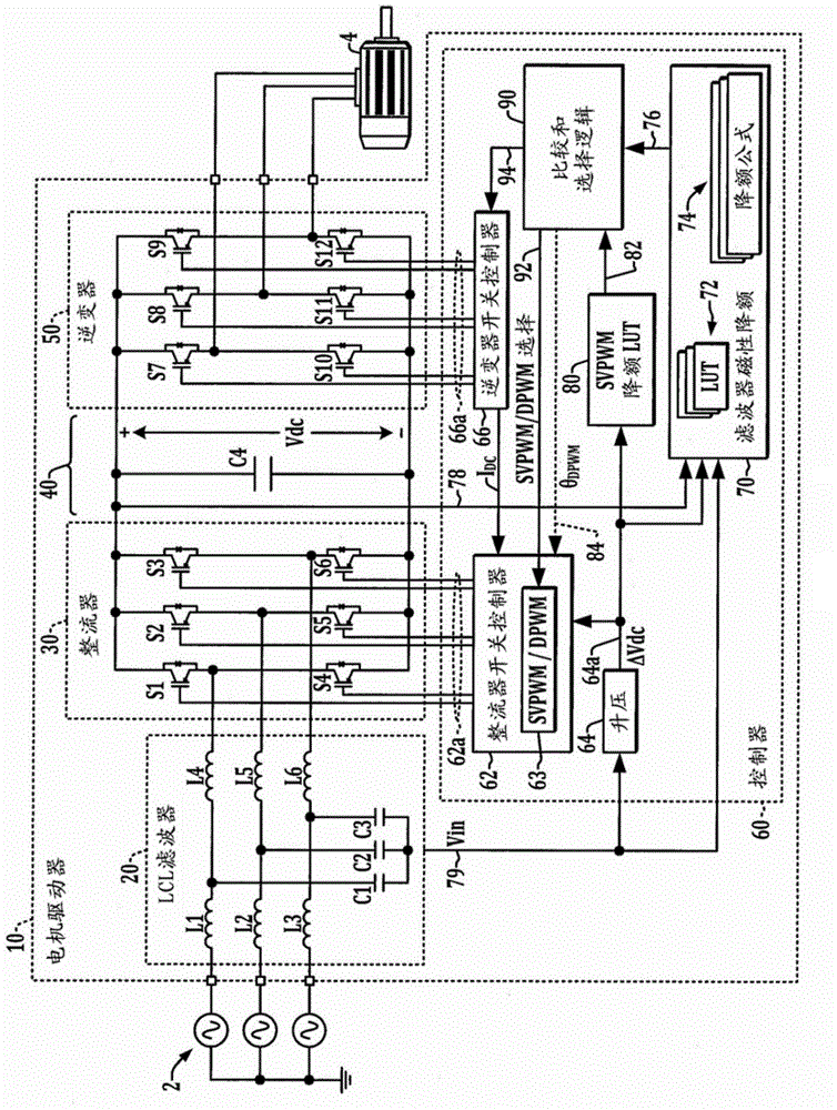
[0019] figure 1 An exemplary motor drive power conversion system 10 is shown that receives single-phase or multi-phase AC input power from an external power source 2 . The example shown receives a three-pha...


PUM


Abstract

Power conversion systems and operating methods are presented in which an active front end rectifier is operated in a boost mode using discontinuous pulse width modulation in a first range of DC bus voltage boost amount, and continuous space vector pulse width modulation is used in a second range, with the ranges being correlated to output derating with respect to filter inductor magnetics in the first range and to rectifier switching loss derating and the second range.

Description

technical field [0001] The present disclosure relates to power conversion systems and methods of operation thereof, and more particularly, to methods and apparatus for continuous and discontinuous active filter boost operation to increase the rating of power converters. Background technique [0002] Power conversion systems are used to provide alternating current (AC) output power to loads such as motor drives, where an inverter stage drives an AC motor. Active front-end (AFE) converters use pulse-width modulated switching rectifiers to convert input AC power and provide direct current (DC) power to the bus, where inverter switches convert the DC bus to output current to drive the load. Such an active front-end converter is usually coupled with an input filter, such as an LCL filter circuit connected to each power phase. Since the front-end rectifier is a switching circuit, the input filter operates to avoid introducing unwanted harmonic content into the grid or other input...

Claims


Application Information

Patent Timeline
IPC IPC(8): H02M5/44H02M7/12
CPCH02M7/219H02M2001/327H02M2001/0022H02M5/4585H02M7/217H02M1/0022H02M1/327Y02B70/10
Inventor 韦立祥约格什·帕特尔
Owner ROCKWELL AUTOMATION TECH
Why Eureka
Try Eureka