Squirrel-cage type two-stage cyclone solid-liquid separation device

A squirrel-cage, liquid separation technology, applied in the direction of separating sediments by centrifugal force, can solve the problems of increased frictional resistance of media, decreased processing efficiency of oil and gas separation equipment, and decreased effective utilization of storage equipment.

Active Publication Date: 2014-09-24
CHINA UNIV OF PETROLEUM (EAST CHINA)
View PDF4 Cites 5 Cited by
  • Summary
  • Abstract
  • Description
  • Claims
  • Application Information

AI Technical Summary

Problems solved by technology

[0002] In the development of onshore and offshore oil and gas fields, a large number of sand particles carried by the production fluid are easy to deposit in the gathering and transportation pipelines and various separation and storage equipment, resulting in blockage of equipment and pipelines, increased wear of pump devices, and the treatment efficiency of oil and gas separation equipment. A series of unfavorable effects such as a sharp decline in the utilization rate of storage equipment and a decrease in the effective utilization rate of storage equipment. For this reason, the efficient separation of solid and liquid in sand-bearing production fluid is a major problem in oil and gas production at home and abroad.
[0003] At present, the solid-liquid separation methods of production fluid containing sand at home and abroad can be summarized into two types: gravity sedimentation method and cyclone separation met

Method used


Image

  • Squirrel-cage type two-stage cyclone solid-liquid separation device
  • Squirrel-cage type two-stage cyclone solid-liquid separation device
  • Squirrel-cage type two-stage cyclone solid-liquid separation device

Examples


Embodiment Construction

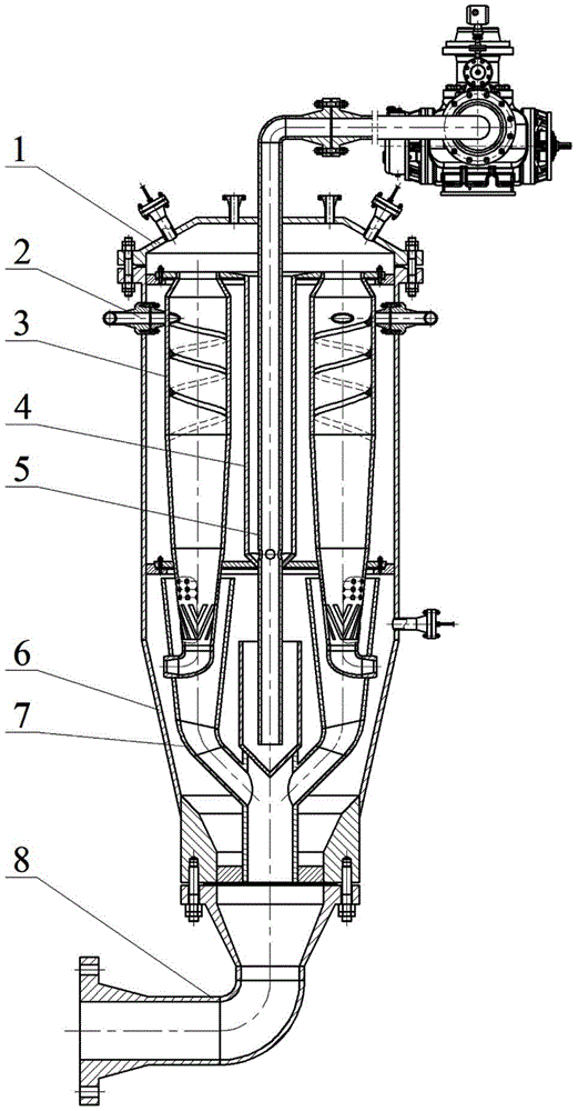
[0033] exist figure 1 Among them, the squirrel-cage two-stage cyclone solid-liquid separation device consists of a sand removal tank 1, a liquid inlet manifold 2, a squirrel-cage cyclone pipe assembly 3, a liquid collection pipe assembly 4, a liquid discharge assembly 5, and a secondary The cyclone tube assembly 6, the sand collection pipe assembly 7 and the sand discharge pipe 8 are composed. When assembling, first weld the lower liquid collecting pipe of the liquid collecting pipe assembly 4 and the sand collecting pipe assembly 7, then put it into the seal of the secondary cyclone assembly 6, and connect the sand discharge pipe 8 to the secondary cyclone assembly 6 through screws. Put the squirrel-cage swirl tube assembly 6 on the upper stage swirl tube assembly 6, then place the lower partition of the squirrel-cage swirl tube assembly 3 into the backing plate, and put the inlet manifold 2 and each swirl tube into the sand removal tank 1 in sequence after welding Inside, c...


PUM


Abstract

The invention provides a squirrel-cage type two-stage cyclone solid-liquid separation device for efficient solid-liquid separation of produced liquid from an oil-gas well. By virtue of squirrel-cage type cyclone pipes and a two-stage cyclone technology, the squirrel-cage type two-stage cyclone solid-liquid separation device is compact in structure and economic in construction cost; the squirrel-cage type cyclone pipes and a two-stage cyclone cylinder assembly sequentially complete first-stage solid-liquid separation and second-stage solid-liquid separation, so that the produced liquid can be efficiently and thoroughly separated. The device is high in adaptability, most of treatment operations are completed by the first-stage solid-liquid separation, and the second-stage solid-liquid separation is used for treating a small amount of remaining liquid under the condition of large liquid quantity and high viscosity; by virtue of the optimized design of all taper sections of the cyclone pipes and two-stage cyclone cylinders, the produced liquid is small in resistance coefficient and is kept in a high-speed rotation state; all the cyclone pipes have the same structure and the same size, so that the standardized and blocked design is realized; separated liquid is collected by a liquid collecting pipe assembly and is discharged from a liquid discharging assembly; sand grains are collected by a sand collecting pipe assembly and a sealing body and then are discharged from a sand discharging pipe; the device is high in degree of automation and easy to install, operate and maintain.

Description

technical field [0001] The invention relates to a device for high-efficiency separation and treatment of solid-liquid production liquids containing sand in land and sea oil and gas wells. Background technique [0002] In the development of onshore and offshore oil and gas fields, a large number of sand particles carried by the production fluid are easy to deposit in the gathering and transportation pipelines and various separation and storage equipment, resulting in blockage of equipment and pipelines, increased wear of pump devices, and the treatment efficiency of oil and gas separation equipment. A series of unfavorable effects such as a sharp decline in the utilization rate of storage equipment and a reduction in the effective utilization rate of storage equipment. For this reason, the efficient separation of solid-liquid in sand-bearing production fluid is a major problem in oil and gas production at home and abroad. [0003] At present, the solid-liquid separation metho...

Claims


Application Information

Patent Timeline
IPC IPC(8): B01D21/26
Inventor 刘春花刘新福陈国龙
Owner CHINA UNIV OF PETROLEUM (EAST CHINA)
Why Eureka
Try Eureka