Supercharge Your Innovation With Domain-Expert AI Agents!

Machining feeding device for engine piston pin

A technology of mechanical processing and feeding device, which is applied in the direction of metal processing, etc., can solve the problems of dirty and messy processing workshops, waste of materials, and easy scattering of materials, etc., and achieve the effect of overall beauty, convenient use, and simple structure

Inactive Publication Date: 2014-09-24
ANHUI JINQINGLONG MACHINERY
View PDF7 Cites 0 Cited by
  • Summary
  • Abstract
  • Description
  • Claims
  • Application Information

AI Technical Summary

Problems solved by technology

[0003] At present, during the machining process of the existing engine piston pins, the feed trough is used to directly feed the materials. This method will easily scatter the materials, causing the processing workshop to be messy, and the feeding speed cannot be adjusted, resulting in waste of materials. Very inconvenient

Method used


Image

  • Machining feeding device for engine piston pin

Examples


Embodiment Construction

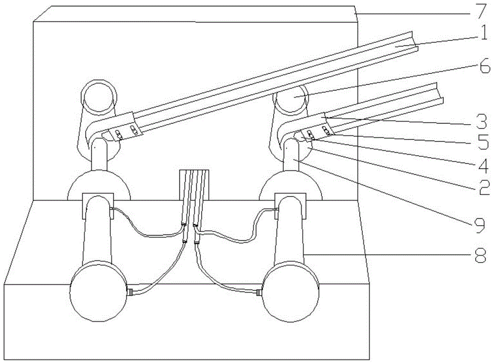
[0014] Such as figure 1 , a mechanical processing feed device for engine piston pins, comprising a feed trough 1, a feed pallet 2, a cover plate 3, and a side baffle 4, and the feed chute 1 is obliquely fixed on the side of a vertically placed processing machine 7 , and extend to the feed port 6, the feed pallet 2 is U-shaped curved, fixed below the feed port 6 and the feed tank 1, the cover plate 3 side is provided with two strip-shaped square The hole 5 is fixed on the feed tank 1 by screws, and is located above the feed tank 1 and the feed pallet 2 as a whole. The side baffle 4 is welded on the outward side of the cover plate 3 .

[0015] Working method: as figure 1 As shown, the material slides freely through the inclined feeding trough 1. There are two elongated square holes 5 on one side of the cover plate 3, which are fixed on the feeding trough 1 by screws, so that the speed of the fed material can be adjusted. The cover plate 3 3 is provided with a side baffle 4 on...


PUM


Abstract

The invention discloses a machining feeding device for an engine piston pin. The machining feeding device for the engine piston pin comprises a feeding chute, a feeding supporting plate, a cover plate and a side baffle, wherein the feeding chute is aslant fixed on the side surface of a vertical processing machine and extends to a material inlet; the feeding supporting plate is fixedly arranged below the material inlet and the feeding trough; one side of the cover plate is provided with two elongated square holes and are fixedly arranged on the feeding trough by screws; the cover plate integrally covers the feeding trough and the feeding supporting plate; the side baffle is positioned above the feeding supporting plate and is welded on the outward side of the cover plate. The machining feeding device for the engine piston pin, which is disclosed by the invention, has the advantages of simple structure, convenience in use and small possibility for fed materials to scatter, and the size of the fed materials can be regulated.

Description

[0001] technical field [0002] The invention relates to machining equipment, in particular to a machining feeding device for engine piston pins. Background technique [0003] At present, during the machining process of the existing engine piston pins, the feed trough is used to directly feed the materials. This method will easily scatter the materials, causing the processing workshop to be messy and messy, and the feeding speed cannot be adjusted, resulting in waste of materials. Very inconvenient. Contents of the invention [0004] The purpose of the present invention is to provide a kind of easy to use, can adjust the feed size, the feed device of the engine piston pin that the feed is not easy to scatter. [0005] The purpose of the present invention can be achieved through the following technical solutions: [0006] A feed device for machining piston pins of an engine comprises a feed groove, a feed support plate, a cover plate and a side baffle. [0007] The feed ...

Claims


Application Information

Patent Timeline
IPC IPC(8): B23Q7/08
CPCB23Q7/08B23Q7/06
Inventor 左克祥刘治盛张国化
Owner ANHUI JINQINGLONG MACHINERY
Features
  • R&D
  • Intellectual Property
  • Life Sciences
  • Materials
  • Tech Scout
  • Unparalleled Data Quality
  • Higher Quality Content
  • 60% Fewer Hallucinations
Learn More