A magnetron bush sputtering machine

A technology of sputtering machine and bearing bush, applied in the field of magnetron bearing bushing sputtering machine, can solve the problems of low output and efficiency, and achieve the effect of increasing work output and improving efficiency

Active Publication Date: 2016-06-08
烟台大丰轴瓦有限责任公司
View PDF6 Cites 0 Cited by
  • Summary
  • Abstract
  • Description
  • Claims
  • Application Information

AI Technical Summary

Problems solved by technology

[0002] Magnetron sputtering is to form an orthogonal electromagnetic field on the surface of the cathode target. The electron density in this area is high, thereby increasing the ion density, so that the sputtering rate is increased (an order of magnitude), and the sputtering speed can reach 0.1-1um / min. The focus is better than evaporation, and it is one of the most practical coating technologies at present. In magnetron sputtering, the usual method of processing standard bearing bushes is: 1. First manufacture the steel back, 2. Sinter or pour a copper-based alloy layer on the steel back , 3. Send the bearing bush substrate into the sputtering equipment for layered sputtering nickel grid layer and friction-reducing alloy layer. This method is safe and environmentally friendly, but the disadvantage is that two layers (nickel grid layer and friction-reducing alloy layer ), limited by the current sputtering equipment, so after sputtering the nickel grid layer, it is necessary to cool down and replace the nickel target with an alloy target. This sputtering method is restricted by steps such as cooling down and replacing the target material. very low

Method used


Image

  • A magnetron bush sputtering machine
  • A magnetron bush sputtering machine

Examples


Embodiment

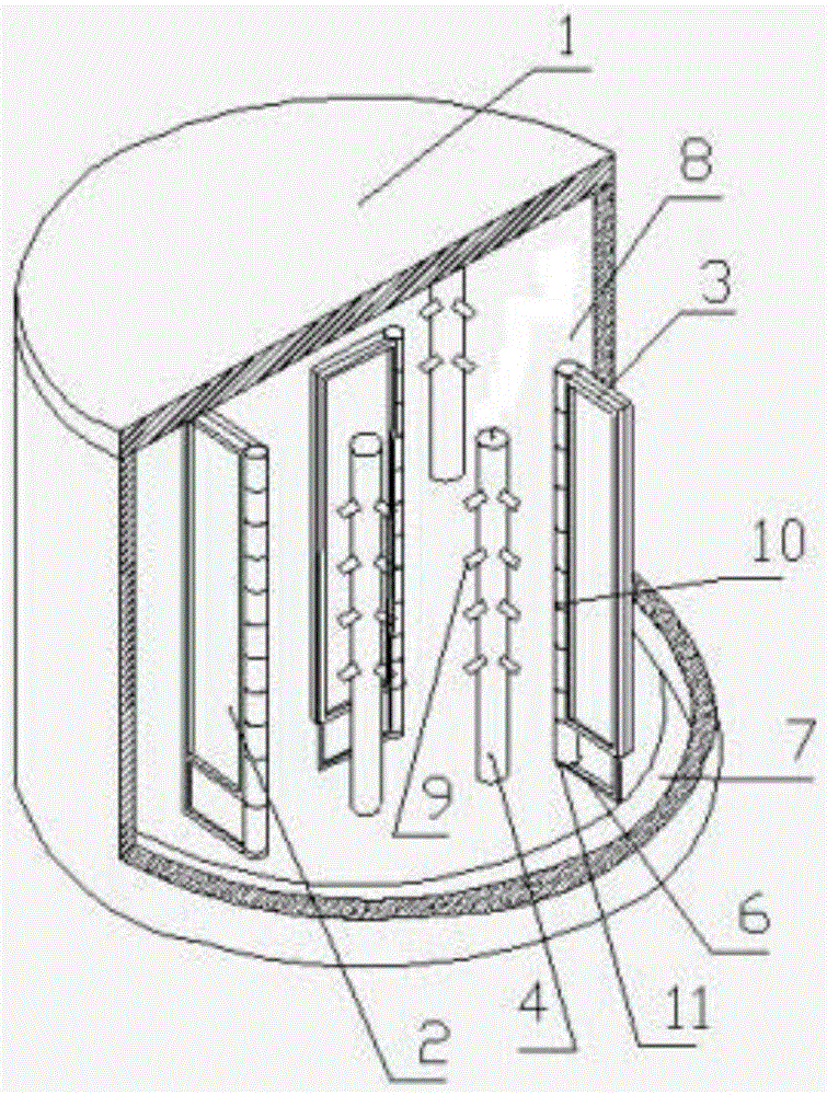
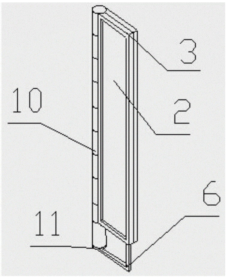
[0014] by reference figure 1 with figure 2 , a magnetron bush sputtering machine, comprising a sputtering shell 1, a sputtering chamber 8 is arranged in the sputtering shell 1, a sputtering target support frame 3 and a bearing bush support frame 4 are arranged in the sputtering chamber 8, and the sputtering The bottom of the shell 1 is provided with a base 7, the sputtering target support frame 3 and the bearing bush support frame 4 are arranged on the base 7 at the bottom of the sputtering shell 1, and the sputtering target support frame 3 is provided with a sputtering target frame shaft 10 in the middle of which the sputtering target support frame 3 is arranged. A rotating ring 11 is provided at the bottom of the target holder shaft 10, and the rotating ring 11 is connected to the edge of the sputtering target support frame 3 on one side of the sputtering target holder shaft 10 through a connecting rod 6. A motor is provided at the bottom of the sputtering shell 1, and the ...


PUM


Abstract

The invention discloses a novel magnetron bearing bush sputtering machine, which relates to the technical field of sputtering devices, and comprises a sputtering housing, in which a sputtering chamber is provided, and the sputtering chamber is provided with a sputtering target support frame and a bearing bush support The bottom of the sputtering shell is provided with a base, the sputtering target support frame and the bearing bush support frame are arranged on the bottom base of the sputtering shell, the sputtering target support frame is provided with a sputtering target frame shaft, and the bottom of the sputtering target frame shaft is A rotating ring is provided, and the rotating ring is connected to the edge of the sputtering target support frame on one side of the sputtering target frame shaft through a connecting rod. There is a motor at the bottom of the sputtering shell, and the rotating ring is connected to the output shaft of the motor. The sputtering target frame The sputtering target support frame on both sides of the shaft is equipped with a sputtering target, and the two sides of the sputtering target are provided with grooves. The bottom surface of the front groove is a nickel target, and the bottom surface of the back groove is an alloy target. It solves the constraints of steps such as cooling down and replacing the target in the past, which increases the work output and improves the efficiency.

Description

technical field [0001] The invention relates to a sputtering device, in particular to a magnetron bush sputtering machine. Background technique [0002] Magnetron sputtering is to form an orthogonal electromagnetic field on the surface of the cathode target. The electron density in this area is high, thereby increasing the ion density, so that the sputtering rate is increased (an order of magnitude), and the sputtering speed can reach 0.1-1um / min. The focus is better than evaporation, and it is one of the most practical coating technologies at present. In magnetron sputtering, the usual method of processing standard bearing bushes is: 1. First manufacture the steel back, 2. Sinter or pour a copper-based alloy layer on the steel back , 3. Send the bearing bush substrate into the sputtering equipment for layered sputtering nickel grid layer and friction-reducing alloy layer. This method is safe and environmentally friendly, but the disadvantage is that two layers (nickel grid ...

Claims


Application Information

Patent Timeline
Patent Type & Authority Patents(China)
IPC IPC(8): C23C14/35
Inventor 木俭朴
Owner 烟台大丰轴瓦有限责任公司
Why Eureka
Try Eureka