A high vacuum magnetron bush sputtering machine

A high-vacuum, sputtering machine technology, applied in the direction of vacuum evaporation plating, sputtering plating, ion implantation plating, etc., can solve the problems of low output, low efficiency, serious pollution and human injury, etc., to increase work output, improve efficiency effect

Active Publication Date: 2017-08-15
烟台大丰轴瓦有限责任公司
View PDF6 Cites 0 Cited by
  • Summary
  • Abstract
  • Description
  • Claims
  • Application Information

AI Technical Summary

Problems solved by technology

[0002] At present, standard bearings are divided into four layers: steel back, copper-based alloy sintered on the steel back, nickel grid layer, anti-friction alloy layer, the usual method of processing standard bearings is: 1. First manufacture the steel back, 2. On the steel back Sinter or pour the copper-based alloy layer on the back, 3, electroplate the nickel grid layer on the copper-based alloy layer, and 4, send it into the sputtering equipment to sputter the anti-friction alloy layer. The disadvantage of this method is: in the method steps Including the electroplating method, which is a processing method with serious pollution and great harm to the human body. Another method of processing standard bearing bushes is: 1. Manufacturing the steel back first, 2. Sintering or pouring a copper-based alloy layer on the steel back, 3. The bearing substrate is sent to the sputtering equipment to sputter the nickel grid layer and the friction-reducing alloy layer layer by layer. This method is safe and environmentally friendly, but the disadvantage is that it is subject to The current sputtering equipment is limited, so after sputtering the nickel grid layer, it is necessary to cool down and replace the nickel target with an alloy target. This sputtering method is restricted by steps such as cooling and target replacement, and the output and efficiency are very low.

Method used


Image

  • A high vacuum magnetron bush sputtering machine
  • A high vacuum magnetron bush sputtering machine

Examples


Embodiment

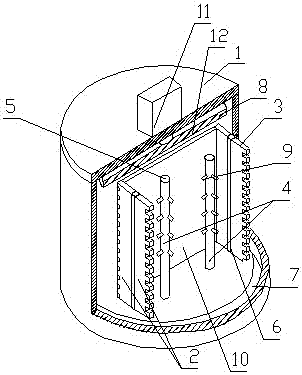
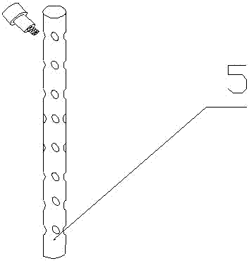
[0017] by reference figure 1 with figure 2 , a high-vacuum magnetron bearing bush sputtering machine, comprising a sputtering housing 1, a sputtering chamber 8 is arranged in the sputtering housing 1, and the sputtering chamber 8 is provided with a sputtering target 2 and a bearing bush support frame 4, The bottom of the sputtering housing 1 is provided with a base 7, and the base 7 is provided with a sputtering target frame rotating shaft 6, and the sputtering target frame rotating shaft 6 is fixedly provided with a sputtering frame for moving the sputtering target 2. A target support frame 3, the sputtering target 2 is a double-sided target, the front is a nickel target, and the back is an alloy target. The middle of the sputtering target support frame 3 is fixedly connected with a sputtering target frame rotating shaft 6, and The edge is concave-convex and serrated, and a baffle 10 is also provided on the base 7. The edge of the baffle is provided with concave-convex and ...


PUM


Abstract

The invention discloses a high-vacuum magnetron bearing bush sputtering machine, which relates to the technical field of sputtering devices. The structure includes a sputtering shell, in which a sputtering chamber is arranged, and the sputtering chamber is provided with a sputtering target and a bearing bush support. The bottom of the sputtering shell is provided with a base, the base is provided with a sputtering target frame rotation axis, and the sputtering target frame rotation axis is fixed with a sputtering target support frame for moving the sputtering target. The sputtering target is Double-sided target, the front is a nickel target, the back is an alloy target, the middle of the sputtering target support frame is fixedly connected with the rotation axis of the sputtering target frame, the edges on both sides are concave-convex and serrated, and a baffle 10 is also provided on the base 7 The edge of the baffle plate is provided with concave-convex zigzags that match the sputtering target support frame 3 in a concave-convex zigzag shape. The hanging column of the bearing bush, this sputtering method is safe and environmentally friendly. By setting a rotatable double-sided target, it solves the constraints of cooling and replacing the target in the past, which increases the work output and improves the efficiency.

Description

technical field [0001] The invention relates to a sputtering device, in particular to a high-vacuum magnetron bush sputtering machine. Background technique [0002] At present, standard bearings are divided into four layers: steel back, copper-based alloy sintered on the steel back, nickel grid layer, and anti-friction alloy layer. Usually, the method of processing standard bearings is: 1. First manufacture the steel back, 2. On the steel back Sinter or pour the copper-based alloy layer on the back, 3, electroplate the nickel grid layer on the copper-based alloy layer, and 4, send it into the sputtering equipment to sputter the anti-friction alloy layer. The disadvantage of this method is: in the method steps Including the electroplating method, which is a processing method with serious pollution and great harm to the human body. Another method of processing standard bearing bushes is: 1. Manufacturing the steel back first, 2. Sintering or pouring a copper-based alloy layer ...

Claims


Application Information

Patent Timeline
Patent Type & Authority Patents(China)
IPC IPC(8): C23C14/35
Inventor 木俭朴
Owner 烟台大丰轴瓦有限责任公司
Why Eureka
Try Eureka