
A logic control circuit for automatic pressurization of full hydraulic long auger drilling rig

A long auger drilling rig, logic control technology, applied in the automatic control system of drilling, fluid pressure actuating device, drilling equipment, etc., can solve the problems of fragile wire rope, loose strands of pressurized hoisting wire rope, and chaotic winding of wire rope, etc. Achieve the effect of preventing scattered stocks and reducing labor intensity

Active Publication Date: 2016-06-01
CHTC JOVE HEAVY IND
View PDF6 Cites 0 Cited by
  • Summary
  • Abstract
  • Description
  • Claims
  • Application Information

AI Technical Summary

Problems solved by technology

When actively using the main winch to lower the power head or use the self-weight of the drill pipe to pressurize the drilling, the wire rope of the pressurized winch will have loose strands. When the power head is raised again, the wire rope on the pressurized winch drum will be entangled Messy and therefore prone to damage to the wire rope

Method used


Image

  • A logic control circuit for automatic pressurization of full hydraulic long auger drilling rig
  • A logic control circuit for automatic pressurization of full hydraulic long auger drilling rig

Examples


Embodiment Construction

[0017] Embodiments of the present invention will be described in detail below in conjunction with the accompanying drawings, but they are not used to limit the scope of the present invention.

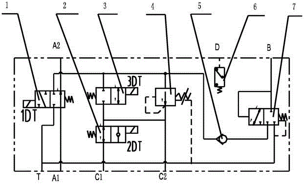
[0018] like figure 1 As shown, the automatic pressurization logic control circuit of the full hydraulic long auger drill consists of a two-position four-way electromagnetic directional valve 1, a first two-position two-way electromagnetic directional valve 2, a second two-position two-way electromagnetic directional valve 3, and Pressure valve 4, one-way valve 5, pressure relay 6, hydraulic control reversing valve 7. All components are integrated in the hydraulic valve block and connected through the oil passage inside the valve block. Specifically, the hydraulic valve block has a hydraulic oil inlet A1 and a hydraulic oil outlet A2, a power head motor working pressure test port B, a first pressurized hoist inlet C1, a second pressurized hoist inlet C2, a pressure test port D and the ...


PUM


Abstract

The invention discloses a pressurization logic control loop of an all-hydraulic long spiral drilling machine using a hydraulic valve block. The automatic-pressurization logic control loop is characterized in that a pressure oil outlet of a main winch motor is connected with a pressure testing port (D) of the hydraulic valve block by a hydraulic pipeline; hydraulic oil outputted by a first hydraulic pump is connected with a hydraulic oil inlet (A1) of the hydraulic valve block by a six-way valve, is led out from a hydraulic oil outlet (A2) of the hydraulic valve block, and is connected into a power-head motor inlet by a first one-way valve and a first main oil path; the power-head motor inlet is led to a working-pressure testing port (B) of the power-head motor of the hydraulic valve block by a hydraulic pipeline; a pressurizing winch motor inlet is connected into a first pressurizing winch inlet (C1) of the hydraulic valve block by the six-way valve; a pressurizing winch motor outlet is connected with a second pressurizing winch inlet (C2) of the hydraulic valve block. The automatic-pressurization logic control loop disclosed by the invention has the advantages that when a main winch is actively utilized for falling the power head or the self weight of a drilling rod is utilized for pressurizing and drilling and the main winch follows, a pressurizing winch can realize automatic pressurization, so that the bundle dispersion of steel wire ropes is prevented; when a hard-soil layer is met, the pressurizing winch can realize automatic pressurization, so that the power head obtains larger torque.

Description

technical field [0001] The invention relates to an automatic pressurization logic control circuit of a full hydraulic long auger drilling rig. Background technique [0002] When drilling a full hydraulic long helical drilling rig, the pressurized winch is used to apply downward pressure on the power head or the self-weight of the drill pipe to press down. The hydraulic motor drives the drill pipe to rotate and drill through the power head reducer. At this time, the main The winch is in the follow-up state, and the main winch wire rope is lowered freely following the power head; after the drilling is completed, the main winch exerts an upward lifting force on the power head to lift the drill pipe out of the hole. In the dynamic state, the pressurized hoisting wire rope follows the power head to rise freely. When actively using the main winch to lower the power head or use the self-weight of the drill pipe to pressurize the drilling, the wire rope of the pressurized winch wil...

Claims


Application Information

Patent Timeline
Patent Type & Authority Patents(China)
IPC IPC(8): E21B44/06F15B13/06F15B11/16
Inventor 杨浪凌国滨肖国兴
Owner CHTC JOVE HEAVY IND
Learn More