
Engine muffler
A muffler and engine technology, applied to engine components, machines/engines, noise reduction devices, etc., can solve problems such as short exhaust pipes, achieve the effects of improving air tightness, improving welding quality, and ensuring quality
- Summary
- Abstract
- Description
- Claims
- Application Information
AI Technical Summary
Problems solved by technology
Method used
Image

Examples
Embodiment 1
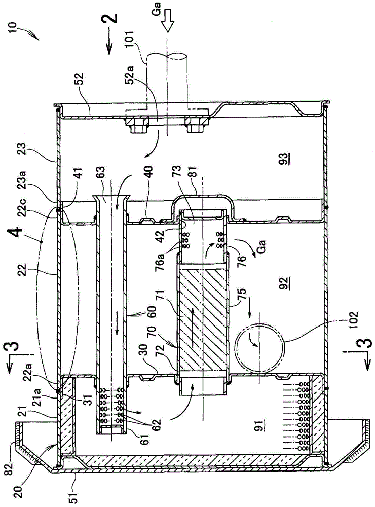
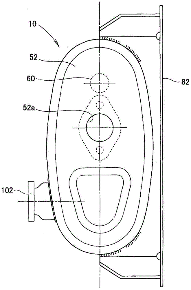
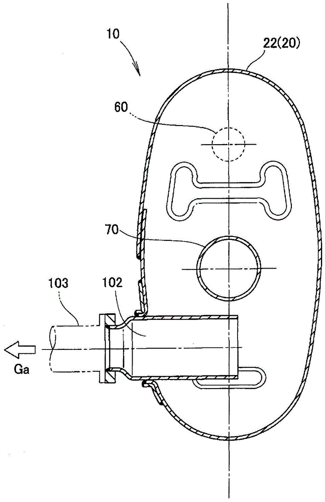
[0035] The muffler for an engine according to the embodiment will be described. like Figure 1 ~ Figure 3 As shown, the muffler 10 for an engine is particularly suitable for muffler of the exhaust sound of a general-purpose engine not shown, and at least one (for example, two) partition wall plates 30, 40 are used to separate the cylindrical muffler main body 20 The internal partition has a structure of a plurality of expansion chambers 91 to 93 in the longitudinal direction. Hereinafter, this muffler 10 for an engine is simply referred to as "the muffler 10".
[0036] Described in detail, the muffler 10 is composed of the following parts: 1 muffler main body 20; 2 partition wall plates 30, 40; 2 end plates 51, 52 that block the two ends of the muffler main body 20; 2 communication pipes 60, 70; and 1 cover 81. Furthermore, this muffler 10 has a bracket 82 for attaching it to an arbitrary component.
[0037] The muffler main body 20 is composed of a tube with a circular cr...
Embodiment 2
[0062] based on Figure 8 The muffler for an engine of Example 2 will be described. Embodiment 2 is characterized in that the above-mentioned Figure 1 to Figure 7 The muffler 10 for the engine shown in Embodiment 1 is changed to Figure 8 The muffler 10A for the engine shown in, other structures are the same as the above Figure 1 to Figure 7 The structures shown in are the same, so explanations are omitted.
[0063] Specifically, the engine muffler 10A of the second embodiment is characterized in that the joint structure in which the opposing ends 22c, 23a of the second and third split bodies 22, 23 are joined to the second partition wall plate 40 is performed. change. And, for the above figure 1 The joint structure in which the end portions 21a, 22a of the first and second divided bodies 21, 22 facing each other and the first partition wall plate 30 are joined to each other can also be changed in the same manner.
[0064] Figure 8 (a) shows the state which disassemb...
Embodiment 3
[0069] based on Figure 9 The muffler for an engine of Example 3 will be described. Embodiment 3 is characterized in that the above-mentioned Figure 8 The muffler 10A for the engine shown in Embodiment 2 is changed to Figure 9 The muffler 10B for the engine shown in , other structures are the same as the above Figure 8 The structures shown in are the same, so explanations are omitted.
[0070] Specifically, the second annular portion 41 of the engine muffler 10B of the third embodiment is characterized in that the extension portion 44 of the above-mentioned second embodiment is eliminated.
[0071] Figure 9 (a) shows the state which disassembled the 2nd and 3rd division|segmentation body 22,23 and the 2nd partition wall plate 40. Figure 9 (b) means adding the above Figure 9 A structure formed by combining the components shown in (a).
[0072] like Figure 9 As shown, the second annular portion 41 of the second partition wall plate 40 of the third embodiment inclu...
PUM
 Abstract
Description
Claims
Application Information