
Three-dimensional magnetic flux leakage imaging detecting floated magnetizing component for pipeline

An imaging detection and pipeline technology, which is applied in the pipeline system, magnetic objects, electrical components, etc., can solve the problems of the magnetic circuit structure of the detector to be improved, the detector's attitude is incorrect, and the deformation adaptability is poor, so as to improve the passing ability and Deformation adaptability, simple structure and good applicability

Active Publication Date: 2014-09-24
TSINGHUA UNIV
View PDF7 Cites 8 Cited by
  • Summary
  • Abstract
  • Description
  • Claims
  • Application Information

AI Technical Summary

Problems solved by technology

Although the support strength of the magnetic circuit structure is good, the adaptability to deformation is poor, and the environment inside the pipeline is complex, which will generate a lot of noise and interference during the detection process, which will easily lead to incorrect attitude of the detector, which may cause the detector to jam the pipeline
Therefore, the detector magnetic circuit structure needs to be improved

Method used


Image

  • Three-dimensional magnetic flux leakage imaging detecting floated magnetizing component for pipeline
  • Three-dimensional magnetic flux leakage imaging detecting floated magnetizing component for pipeline
  • Three-dimensional magnetic flux leakage imaging detecting floated magnetizing component for pipeline

Examples


Embodiment Construction

[0031] Embodiments of the present invention are described in detail below, examples of which are shown in the drawings, wherein the same or similar reference numerals designate the same or similar elements or elements having the same or similar functions throughout. The embodiments described below by referring to the figures are exemplary and are intended to explain the present invention and should not be construed as limiting the present invention.

[0032] In describing the present invention, it should be understood that the terms "center", "longitudinal", "transverse", "length", "width", "thickness", "upper", "lower", "front", " Rear", "Left", "Right", "Vertical", "Horizontal", "Top", "Bottom", "Inner", "Outer", "Axial", "Radial", "Circumferential" The orientation or positional relationship indicated by etc. is based on the orientation or positional relationship shown in the drawings, and is only for the convenience of describing the present invention and simplifying the de...


PUM

PropertyMeasurementUnit
lengthaaaaaaaaaa
thicknessaaaaaaaaaa
thicknessaaaaaaaaaa

Abstract

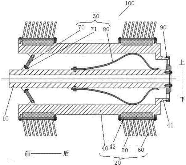
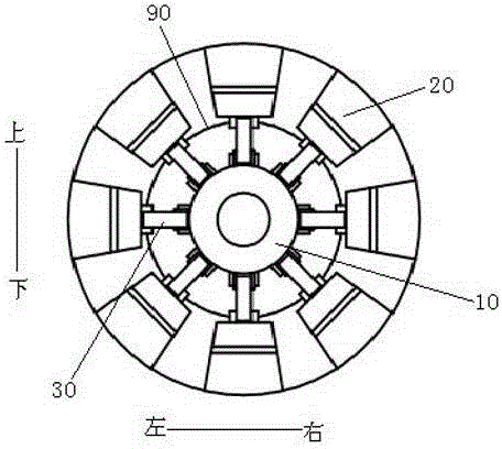
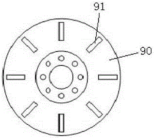
The invention discloses a three-dimensional magnetic flux leakage imaging detecting floated magnetizing component for a pipeline. The floated magnetizing component comprises a mandrel, a plurality of floated magnetizing blocks and a plurality of supporting components, wherein the floated magnetizing blocks are arranged between the outer wall surface of the mandrel and the inner wall surface of the pipeline, and uniformly separated in the circumference direction of the mandrel; at least one part of each floated magnetizing block is propped against the inner wall surface of the pipeline; the floating and magnetizing block comprises a magnetizer, two magnetic pieces and a plurality of silicon steel sheets; the magnetizer extends in the axial direction of the mandrel and is column-shaped; the two magnetic pieces are respectively arranged on the outer wall surface of the magnetizer and arranged at an interval in the front-back direction; the silicon steel sheets are respectively connected with the two magnetic pieces; the free ends of the silicon steel sheets are respectively propped against the inner wall surface of the pipeline; the supporting components are respectively and movably arranged between the floated magnetizing blocks and the outer wall surface of the mandrel; each supporting component is propped against the inner wall surface of the magnetizer and the outer wall surface of the mandrel. The component is good in magnetoconductivity, simple in structure, good in applicability, and accurate in detection.

Description

technical field [0001] The present invention relates to the technical field of oil and gas pipeline detection, in particular, to a method for on-line detection of defects in oil and gas pipelines and a magnetic circuit structure design method, and more specifically, to a floating magnetized assembly for pipeline three-dimensional magnetic flux leakage imaging detection. Background technique [0002] With the development of oil and gas extraction technology, the supporting oil and gas pipeline transportation technology is also constantly improving. In particular, the turning radius of the oil and gas pipeline is small, only 1.5D (D is the diameter of the pipeline), which has a very high test on the passability of the detector, and the difficulty of magnetization increases. This requires the three-dimensional magnetic flux leakage imaging detector of oil and gas pipelines to have high passing capacity, deformation adaptability and magnetization reliability. Reasonable magnetic...

Claims


Application Information

Patent Timeline
Patent Type & Authority Applications(China)
IPC IPC(8): F17D5/02H01F13/00
Inventor 黄松岭王珅赵伟刘欢
Owner TSINGHUA UNIV
Learn More