
Elastic supporting device vibration strain monitoring method

A technology of vibration strain and elastic support, which is applied in the direction of vibration measurement in solids, measuring vibration, instruments, etc., can solve the problem that the squeeze oil film damper of the elastic support can not work reliably in the oil film linear region, The vibration information of the casing can not be accurately reflected and other problems, so as to achieve the effect of friendly man-machine interface, improve safe operation performance, and avoid inaccurate detection

Inactive Publication Date: 2014-09-24
CHINA AVIATION POWER MACHINE INST
View PDF2 Cites 24 Cited by
  • Summary
  • Abstract
  • Description
  • Claims
  • Application Information

AI Technical Summary

Problems solved by technology

[0004] The purpose of the present invention is to provide a method for monitoring the vibration and strain of an elastic support, so as to solve the problem that the vibration information of the existing casing cannot accurately reflect the vibration strain of the elastic support and the extrusion oil film damper of the elastic support cannot reliably work in the oil film linear District Technical Issues

Method used


Image

  • Elastic supporting device vibration strain monitoring method
  • Elastic supporting device vibration strain monitoring method
  • Elastic supporting device vibration strain monitoring method

Examples


Embodiment Construction

[0032] The embodiments of the present invention will be described in detail below with reference to the accompanying drawings, but the present invention can be implemented in many different ways defined and covered by the claims.

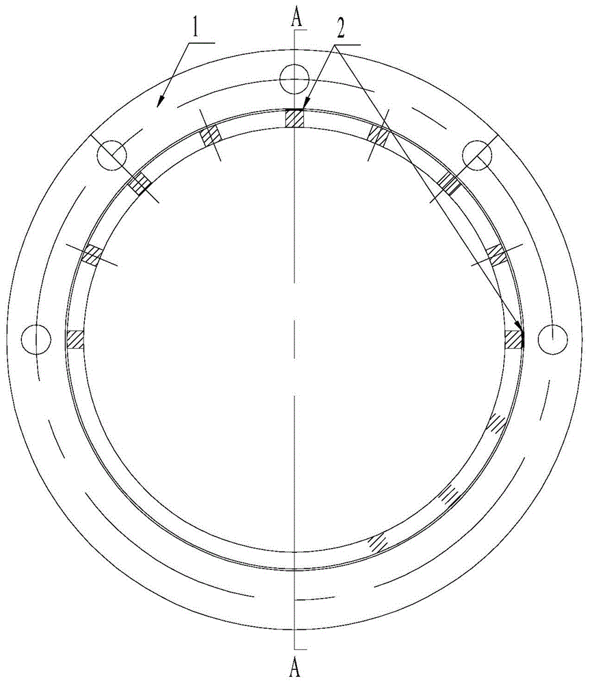
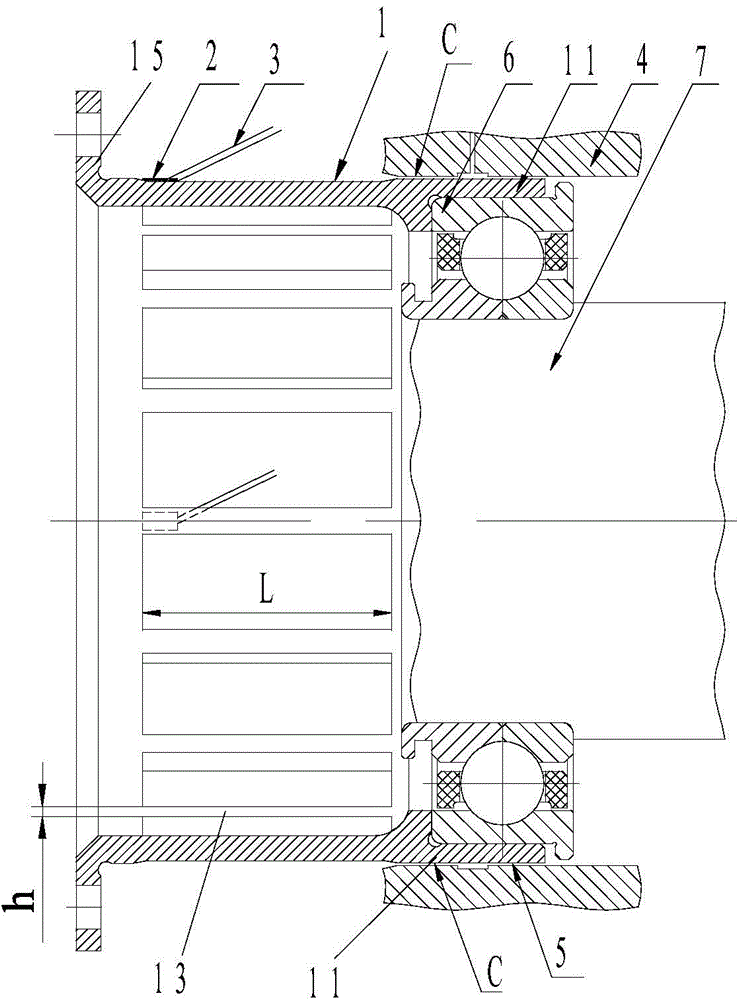
[0033] A preferred embodiment of the present invention provides a method for monitoring vibration and strain of an elastic support, referring to figure 2 and image 3 , in the embodiment of the present invention, the support body of the elastic support 1 includes a bearing seat 11 and a plurality of elastic cage bars 13 distributed along the circumference of the bearing seat 11, and the ends of the plurality of elastic cage bars 13 are along the radial direction of the support body Extending outward to form a mounting edge 15, a gap is formed between the circumferential outer wall of the bearing housing and the casing 4, and the gap is filled with lubricating oil to form the squeeze oil film damper 5; in this embodiment, the oil film of the squeeze...


PUM


Abstract

The invention discloses an elastic supporting device vibration strain monitoring method. A supporting body of an elastic supporting device comprises a bearing pedestal and a plurality of elastic cage strips which are distributed in the circumferential direction of the bearing pedestal, wherein one end of each elastic cage strip outwards extends in the radial direction of the supporting body to form an installation edge, and a gap is formed between the circumferential outer wall of the bearing pedestal and a machine box and filled with lubricating oil so as to form an extruded oil film damper. The method includes the steps that a strain gauge is attached to at least one elastic cage strip and connected to a vibration strain measuring instrument outside the machine box through a lead, and the vibration strain value of the strain gauge is detected through the vibration strain measuring instrument; whether the detected vibration strain value is larger than the preset vibration strain alarm threshold value or not is judged, and an alarm signal is generated if yes. By detecting the vibration strain value of the strain gauge, the vibration strain of the elastic supporting device is accurately detected, it is ensured that a journal of the bearing pedestal works within an extruded oil film linear area, an alarm is given once the vibration strain value exceeds the threshold value, and safe running performance of a rotor is improved.

Description

technical field [0001] The invention relates to the field of vibration strain monitoring, in particular to a method for state monitoring and vibration fault identification for high-speed rotor operation of small and medium-sized aviation turboshaft engines. Background technique [0002] For a long time, in the development process of aero-engines, accelerometers or speedometers are installed on the casing to obtain the vibration information transmitted to the casing by the rotor during operation. The specific method is to install the sensor seat at the vertical and horizontal positions near the front and rear fulcrums of the engine, and then install the accelerometer or speedometer on the sensor seat with M5 bolts to realize the vibration monitoring of the engine. [0003] These signals may be sufficient for the vibration monitoring of large and medium-sized aeroengine rotors with rigid support and a rotational speed below 18000r / min. However, these signals are not enough fo...

Claims


Application Information

Patent Timeline
Patent Type & Authority Applications(China)
IPC IPC(8): G01H1/00
Inventor 吴桂娇陈运西王平雷沫枝
Owner CHINA AVIATION POWER MACHINE INST
Learn More