
Magnetic suspension compressor

A compressor and magnetic levitation technology, used in mechanical equipment, machines/engines, liquid fuel engines, etc., can solve the problems of axial sensor detection data data errors, affecting system control accuracy, etc.

Pending Publication Date: 2021-05-11
GREE ELECTRIC APPLIANCES INC
View PDF0 Cites 2 Cited by
  • Summary
  • Abstract
  • Description
  • Claims
  • Application Information

AI Technical Summary

Problems solved by technology

[0005] However, since there is a certain axial distance between the impeller and the oil-repelling sleeve, when the compressor is running, the motor shaft will elongate due to high temperature, resulting in a change in the relative position of the second-stage impeller and the oil-repelling sleeve, resulting in axial There will be errors between the sensor detection data and the actual axial position data of the impeller, which will affect the control accuracy of the system

Method used


Image

  • Magnetic suspension compressor
  • Magnetic suspension compressor
  • Magnetic suspension compressor

Examples


Embodiment Construction

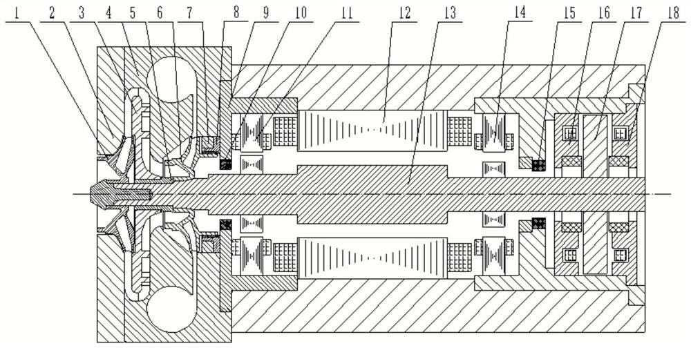
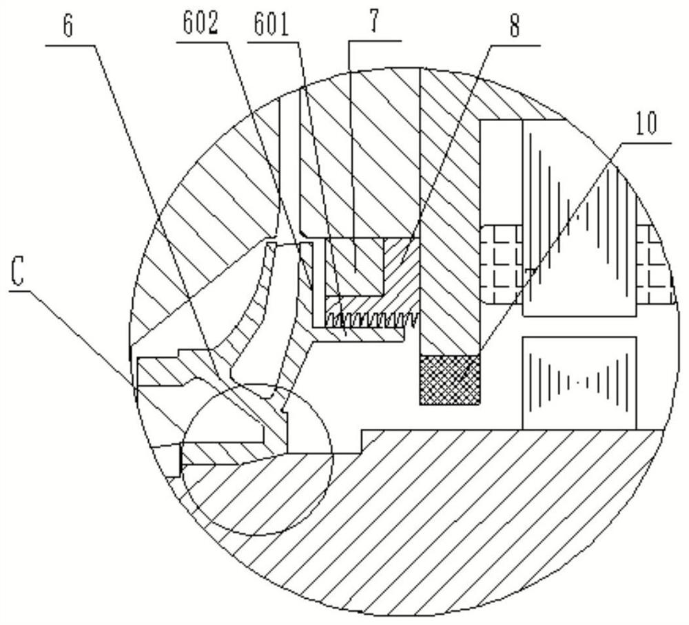
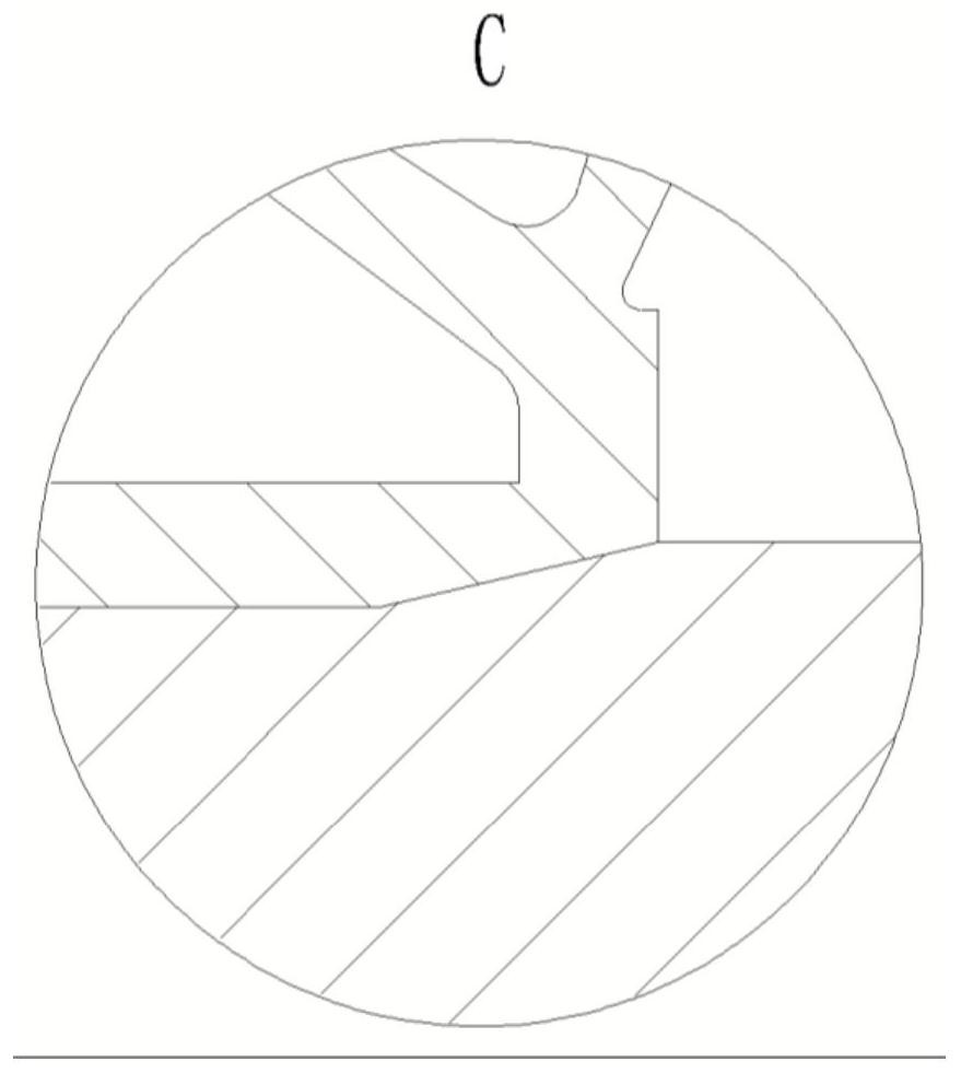
[0025] see in conjunction Figure 1 to Figure 5 As shown, according to the embodiment of the present application, the maglev compressor includes a motor main shaft 13, a first impeller 6, a reflux device 4, an axial displacement sensor 7 and a housing 9, the motor main shaft 13 is installed in the housing 9, and the reflux device 4 It is fixedly connected with the casing 9, the first impeller 6 is installed in the reflux device 4, and is sleeved outside the motor main shaft 13, the axial displacement sensor 7 is fixedly arranged relative to the casing 9, and the first impeller 6 is axially displaced One side of the sensor 7 has an axial detection surface 602 , and the axial displacement sensor 7 can detect the axial displacement of the first impeller 6 through the axial detection surface 602 .

[0026] The axial displacement sensor 7 of the magnetic levitation compressor is distributed on the back side of the first impeller 6, and directly detects the axial displacement of the...


PUM


Abstract

The invention provides a magnetic suspension compressor. The magnetic suspension compressor comprises a motor main shaft (13), a first impeller (6), a backflow device (4) and an axial displacement sensor (7), wherein the first impeller (6) is installed in the backflow device (4) and arranged outside the motor main shaft (13) in a sleeving manner; the axial displacement sensor (7) is fixedly arranged relative to the backflow device (4); one side, facing the axial displacement sensor (7), of the first impeller (6) is provided with an axial detection surface (602); and the axial displacement sensor (7) can detect the axial displacement of the first impeller (6) through the axial detection surface (602). According to the magnetic suspension compressor provided by the invention, the axial position of the impeller can be directly detected, so that the control precision of a system is improved.

Description

technical field [0001] The present application relates to the technical field of air compression, in particular to a magnetic levitation compressor. Background technique [0002] The impeller pressure ratio of the compressor is generally relatively high, which will cause a large axial force on the compressor rotor. In order to reduce the load on the thrust bearing, a balance plate structure is generally installed on the rotor to balance part of the axial force. . For the magnetic levitation compressor, the balance disc is also set for the consideration of reducing the axial magnetic bearing load, and the magnetic levitation compressor generally adopts indirect control when controlling the position of the impeller, by controlling a certain part of the axial component such as The position of the oil resistance sleeve in turn controls the position of the impeller. [0003] The structure of the magnetic levitation centrifugal compressor in the prior art includes a reflux devic...

Claims


Application Information

Patent Timeline
IPC IPC(8): F04D17/12F04D27/00F04D29/051F04D29/058
CPCF04D17/122F04D27/001F04D29/058F04D29/051
Inventor 张芳龚高邹志堂李欣邓明星钟敦颖
Owner GREE ELECTRIC APPLIANCES INC
Learn More