Simulation experiment method for researching relation between seepage field and temperature field of dam

A technology for simulating experiments and seepage fields, applied in thermometers, thermometers with physical/chemical changes, permeability/surface area analysis, etc. problem, to achieve the effect of improving the temperature measurement accuracy

Inactive Publication Date: 2014-09-24
NANJING HYDRAULIC RES INST
View PDF2 Cites 8 Cited by
  • Summary
  • Abstract
  • Description
  • Claims
  • Application Information

AI Technical Summary

Problems solved by technology

However, this measurement method has the following defects: 1. The multiple wires used to connect to multiple temperature probes will form a "meridian" structure inside the model dam body, which will affect the fidelity of the model dam body and affect the quality of the model dam body. The accuracy and reduction of the experiment; 2. The temperature measurement resolution of the traditional temperature sensor is not high, the accuracy is not high and the precision is not high
For example, the Chinese patent application with the publication number CN103364321 discloses: "A distributed optical fiber test platform for monitoring the seepage condition of earth-rock dams, including a heating system, a seepage system and a DTS system; And a highly operable practical platform for dam seepage monitoring" Although this kind of expe

Method used


Image

  • Simulation experiment method for researching relation between seepage field and temperature field of dam
  • Simulation experiment method for researching relation between seepage field and temperature field of dam
  • Simulation experiment method for researching relation between seepage field and temperature field of dam

Examples


Embodiment 1

[0040] In this embodiment, the simulation experiment for studying the relationship between the dam seepage field and the temperature field includes the following steps:

[0041]A. Build a model dam body, such as figure 2 As shown, a dam is built in a flume 1 with a head difference between the upstream and downstream and used to simulate the actual river course. The model dam body 2 is blocked between the upper and lower reaches of the water tank 1 . Both sides of the water tank 1 are plexiglass, the bottom of the water tank 1 is a steel plate, and the top is open;

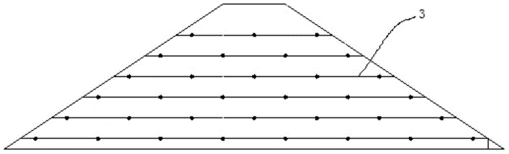
[0042] Such as image 3 As shown, when building the dam, fill the first layer of sand with a thickness of 5 cm at the preset position on the bottom plate of the tank 1, and lay the temperature-sensing optical fiber 3 in the DTS system on the first layer of sand in an S-shape. Cover the second layer of sand on the first layer of sand, and then pull the temperature-sensing optical fiber 3 to the second layer of s...

Embodiment 2

[0068] The experimental method in this embodiment is that the parameters are appropriately changed relative to the first embodiment, including the following experimental steps:

[0069] A. Build a dam on the bottom plate of the flume 1 used to simulate the actual river course. Both sides of the water tank 1 are plexiglass, the bottom of the water tank 1 is a steel plate, and the top is open. Fill the first layer of sand with a thickness of 5 cm at the preset position on the bottom plate of the water tank 1, and lay the temperature-sensing optical fiber 3 in the DTS system on the first layer of sand in an S-shape. Such as image 3 As shown, cover the second layer of sand on the first layer of sand, then pull the temperature-sensing optical fiber 3 onto the second layer of sand and lay it in the same S-shape, and build up layer by layer until the model dam body 2 is built. The temperature-sensitive optical fiber 3 is buried in 6 layers in the model dam body 2 . The material o...

Embodiment 3

[0076] Since the experimental water tank 1 is relatively narrow, in order to reduce the influence of the external temperature on the temperature measurement of the optical fiber section, it is beneficial to further draw a smooth temperature field curve, as shown in Figure 11 As shown, on the basis of the above-mentioned embodiment, the stretch length of the temperature-sensing optical fiber 3 in the temperature-measuring ring 4 in this embodiment is 3m, and the temperature-measuring ring 4 is twisted and bundled into a smooth "8" shape, "8" The curvature of any part of the font is less than 0.05mm -1 . When the optical fiber is laid, the length direction of the "8"-shaped temperature measuring ring 4 is set to be consistent with the length direction of the model dam body 2 . In addition, the average temperature of the last 1.5m of the 3m is used as the approximate temperature of the measuring point.

[0077] The transformation that can also be carried out is: the stretched ...


PUM

PropertyMeasurementUnit
Lengthaaaaaaaaaa
Permeability coefficientaaaaaaaaaa
Lengthaaaaaaaaaa

Abstract

The invention relates to a simulation experiment method for researching relation between a seepage field and a temperature field of a dam. The method includes following steps: A) constructing the dam; B) arranging a water-storage tank, a heating water tank and a temperature-adjusting water tank at an upstream position of a water tank, transporting water to the tank through a submersible pump, and supplying water to the upstream position during a seepage evolution process for enabling an upstream water level to be maintained at 60-70 cm; C) carrying out a continuous temperature measuring process through optical fibers; D) respectively decreasing the upstream water level to 50 cm and 40 cm and performing the temperature measuring process, which is as same as that in the step C), for 120 min when the water level is 50 cm and for 120 min when the water level is 40 cm; and E) drawing a picture of the measured temperature values and seepage flows. According to the invention, a plurality of temperature-measuring rings are formed on temperature-measuring optical fibers, which are originally straight, in a conventional DTS system so that a problem of an insufficient resolution in measurement of a small-size model dam body with the conventional DTS system can be solved and temperature-measuring precision of the small-size model dam body with a DTS system can be increased.

Description

technical field [0001] The invention relates to a simulation experiment method for studying the relationship between the seepage field and the temperature field of a dam. Background technique [0002] Leakage and piping are the main causes of damage to earth-rock dams. Monitoring the temperature in the dam body is an effective means to detect and identify seepage and leakage. Since Mendez et al. first embedded optical fiber sensors in concrete structures for structural safety inspections in 1989, many countries have Scholars have further promoted the application of this technology in civil and hydraulic engineering. In recent years, with the construction of large-scale water conservancy projects and the requirements of water conservancy modernization, distributed optical fiber temperature sensing technology has been successfully applied to mass concrete temperature and crack monitoring, slope monitoring and face rockfill dam face crack monitoring, distributed optical fiber ...

Claims


Application Information

Patent Timeline
IPC IPC(8): G01N15/08G01K11/32G01K11/324
Inventor 谷艳昌王士军周春煦段祥宝王宏徐小定谢罗峰
Owner NANJING HYDRAULIC RES INST
Why Eureka
Try Eureka