Display panel optical compensation device, display panel and optical compensation method

A display panel, optical compensation technology, applied in static indicators, instruments, etc., can solve the problems of cumbersome operation, unable to achieve mass production, etc., and achieve the effect of flexible operation, fast beat speed and high stability

Active Publication Date: 2014-09-24
BOE TECH GRP CO LTD
View PDF5 Cites 36 Cited by
  • Summary
  • Abstract
  • Description
  • Claims
  • Application Information

AI Technical Summary

Problems solved by technology

[0009] The present invention provides a display panel optical compensation device, a display panel and a display panel optical compensation method to solve the technical problem that the optical compensation method in the prior art is cumbersome to operate and cannot be mass-produced

Method used


Image

  • Display panel optical compensation device, display panel and optical compensation method
  • Display panel optical compensation device, display panel and optical compensation method
  • Display panel optical compensation device, display panel and optical compensation method

Examples


Embodiment Construction

[0045] In order to make the purpose, technical solutions and advantages of the embodiments of the present invention clearer, the technical solutions in the embodiments of the present invention will be clearly and completely described below in conjunction with the drawings in the embodiments of the present invention. Obviously, the described embodiments It is a part of embodiments of the present invention, but not all embodiments. Based on the embodiments of the present invention, all other embodiments obtained by persons of ordinary skill in the art without creative efforts fall within the protection scope of the present invention.

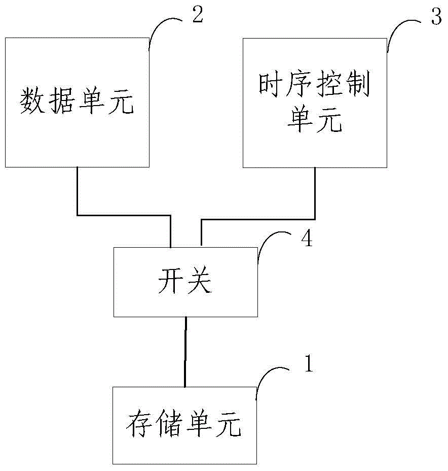
[0046] Embodiments of the present invention firstly provide an optical compensation device for a display panel, see image 3 , including: a storage unit 1 , a data unit 2 , a timing control unit 3 and a switch 4 . in:

[0047] When the switch 4 is placed in the first position, the timing control unit 3 works in the non-compensation mode, and the...


PUM


Abstract

The invention provides a display panel optical compensation device, a display panel and a display panel optical compensation method. The display panel optical compensation device comprises a storage unit, a data unit, a time sequence control unit and a switch, wherein when the switch is in the first position, the time sequence control unit works in a non-compensation mode and carries out non-data exchange with the storage unit, and the data unit receives compensation data and burns the compensation data into the storage unit; when the switch is in the second position, the time sequence control unit works in a compensation mode, reads compensation data in the storage unit to carry out compensation operation on the display data and outputs the compensated display data. The display panel optical compensation device and the display panel are simple in structure, flexible to operate, high in stability, high in speed and suitable for mass production of products.

Description

technical field [0001] The invention relates to the field of display technology, in particular to a display panel optical compensation device, a display panel and a display panel optical compensation method. Background technique [0002] Whether it is an active matrix organic light emitting diode (Active Matrix / Organic LightEmitting Diode, AMOLED) TV or an AMOLED display module, there is a problem of uneven display, that is, there are traces of uneven brightness on the display. It can be seen that its uniformity is relatively poor. [0003] The reason is found that because AMOLED is a current-type light-emitting device, it is greatly affected by the current, and the non-uniformity of the current will cause the non-uniformity of the brightness. However, due to the limitations of the current technology, the uniformity of the backplane is difficult to achieve satisfactory, so the non-uniformity of the current appears. [0004] In addition, the Electro Luminescent (EL) process...

Claims


Application Information

Patent Timeline
Patent Type & Authority Applications(China)
IPC IPC(8): G09G3/32G09G3/3233
CPCG09G3/3225G09G2310/08G09G2320/0233G09G2320/0285G09G2320/0295G09G2360/147
Inventor 解红军
Owner BOE TECH GRP CO LTD
Why Eureka
Try Eureka