Parallel-connection type crystal oscillator

A technology of crystal oscillator and parallel connection, which is applied in the direction of power oscillator, electrical components, etc., can solve the problems of damaged crystal oscillator, waveform distortion, and increase the signal amplitude after oscillation, so as to improve the power filter circuit and reduce the ripple voltage , Improve the effect of the DC component

Inactive Publication Date: 2014-09-24
CHENGDU SHIQI ELECTRONICS TECH
View PDF4 Cites 0 Cited by
  • Summary
  • Abstract
  • Description
  • Claims
  • Application Information

AI Technical Summary

Problems solved by technology

Generally speaking, increasing the current means increasing the power consumption will shorten the start-up time, but at the same time it will increase the amplitude of the signal after the start-up
For the crystal oscillator circuit, if the output signal amplitude is too large, it will not only cause waveform distortion, but also generate too many harmonics, which will affect the performance of the output signal, and the excessive oscillation amplitude will seriously affect the life of the crystal, even Damaged crystal oscillator
In addition, in order to meet the fluctuation of crystal parameters and crystal oscillators of different frequencies, if a fixed current is used to drive the circuit, some crystal oscillators will not vibrate, and some crystal oscillators will have too large amplitude.

Method used


Image

  • Parallel-connection type crystal oscillator

Examples


Embodiment Construction

[0011] The present invention will be further described below in conjunction with accompanying drawing:

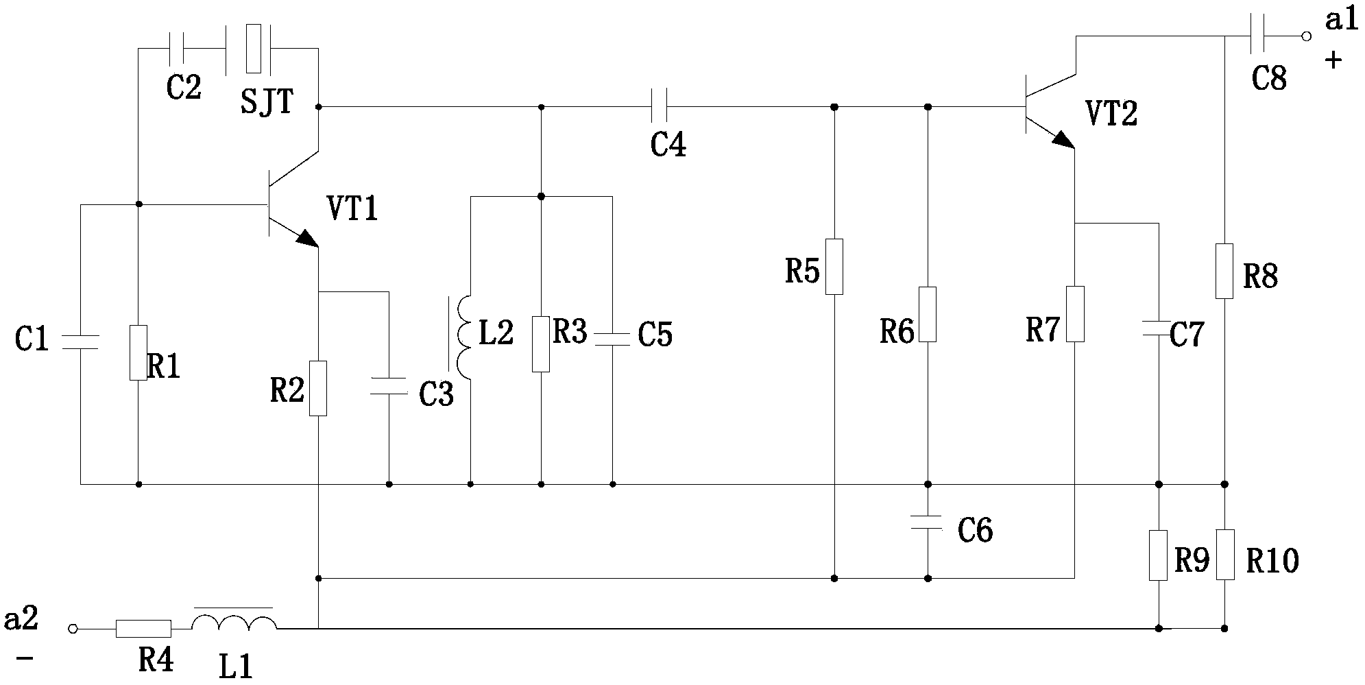
[0012] Such as figure 1 As shown, it includes the positive input terminal a1 of the power supply, the negative output terminal a2 of the power supply, the first resistor R1, the second resistor R2, the third resistor R3, the fourth resistor R4, the fifth resistor R5, the sixth resistor R6, and the seventh resistor R7 , the eighth resistor R8, the ninth resistor R9, the tenth resistor R10, the first capacitor C1, the second capacitor C2, the third capacitor C3, the fourth capacitor C4, the fifth capacitor C5, the first inductor L1, the second inductor L2 , the third inductor L3, the first transistor VT1, the second transistor VT2 and the crystal oscillator SJT, the power input terminal a1 is connected to the first terminal of the eighth capacitor C8, and the second terminal of the eighth capacitor C8 is respectively connected to the set of the second transistor VT2 The elec...


PUM


Abstract

The invention discloses a parallel-connection type crystal oscillator comprising a power supply positive electrode input end, a power supply negative electrode output end, a first resistor, a second resistor, a third resistor, a fourth resistor, a fifth resistor, a sixth resistor, a seventh resistor, an eighth resistor, a ninth resistor, a tenth resistor, a first capacitor, a second capacitor, a third capacitor, a fourth capacitor, a fifth capacitor, a first inductor, a second inductor, a third inductor, a first transistor, a second transistor and a crystal oscillator. A power supply filter circuit can be improved, and control of output signal DC level can be realized so that DC level outputting a sinusoidal signal is constantly ensured to be biased at the preset value in the oscillation process of the crystal oscillator, system stability is guaranteed, ripple voltage is reduced and a DC component is enhanced.

Description

technical field [0001] The invention relates to a crystal oscillator, in particular to a parallel crystal oscillator. Background technique [0002] As a basic circuit module, the crystal oscillator circuit is used in the chip to generate a precise clock signal. This clock signal can not only be mixed with the signal after frequency conversion to realize modulation and demodulation; it can also be used as a reference clock for digital modules. Therefore, crystal oscillators exist in almost every chip and have extremely wide applications. [0003] It takes a relatively long time to start the crystal oscillator (low-frequency crystal oscillators usually need hundreds of milliseconds or even seconds). Generally speaking, increasing the current means increasing the power consumption will shorten the start-up time, but at the same time it will increase the amplitude of the signal after the start-up. For the crystal oscillator circuit, if the output signal amplitude is too large...

Claims


Application Information

Patent Timeline
Patent Type & Authority Applications(China)
IPC IPC(8): H03B5/06H03B5/04
Inventor 陈伟孙国栋
Owner CHENGDU SHIQI ELECTRONICS TECH
Why Eureka
Try Eureka