Cleaning method and device for regenerating of waste denitration catalyst

A technology for denitration catalysts and cleaning devices, which is applied in catalyst regeneration/reactivation, chemical instruments and methods, physical/chemical process catalysts, etc. Effect

Active Publication Date: 2014-10-01
BEIJING GUODIAN LONGYUAN ENVIRONMENTAL ENG +1
View PDF2 Cites 10 Cited by
  • Summary
  • Abstract
  • Description
  • Claims
  • Application Information

AI Technical Summary

Problems solved by technology

The core of the mainstream SCR denitrification technology is the denitrification catalyst

Method used


Image

  • Cleaning method and device for regenerating of waste denitration catalyst

Examples


Embodiment 1

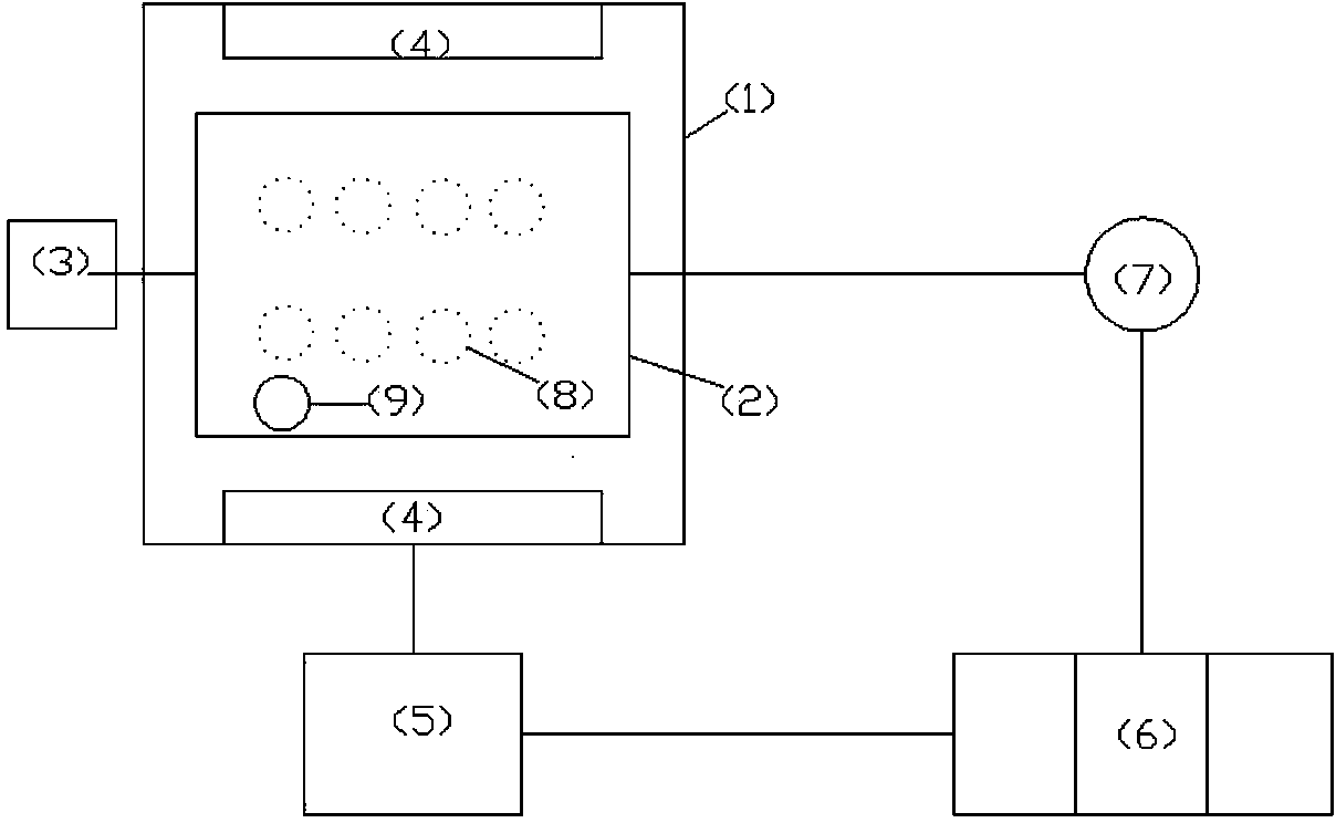
[0027] (1) Take a 2×1×1.2m denitrification catalyst module, whose catalytic efficiency is reduced from 87% to 45%, and place it in the module rotating box 2. The channel direction of the catalyst module is vertical, and a movable high-pressure water gun is used 9. Adjust the pressure to 5MPa to flush the catalyst module channel for 30 minutes; add water until it just submerges the catalyst module channel, and the aeration pipe 8 passes 3kg pressure steam to heat and clean the water in the box 1 to 60°C; the aeration pipe 8 passes 8kg pressure steam Compressed air for water and air cleaning operation; use the geared motor 3 to rotate the module rotation box 2 until the direction of the catalyst module hole is horizontal, and the ultrasonic vibration plate 4 starts and adjusts the frequency to 20kHz to perform ultrasonic cleaning on the catalyst module hole, and the cleaning time is 60min;

[0028] (2) Put the cleaning water in the cleaning tank 1 into the sedimentation tank 5, u...

Embodiment 2

[0034] (1) Take a 2×1×1.2m denitrification catalyst module, whose catalytic efficiency is reduced from 87% to 45%, and place it in the module rotating box 2. The channel direction of the catalyst module is vertical, and a movable high-pressure water gun is used 9 Adjust the pressure to 10MPa to flush the catalyst module channel for 45 minutes; add water until it just submerges the catalyst module channel, and the aeration pipe 8 passes 3kg pressure steam to heat and clean the water in the box 1 to 70°C; the aeration pipe 8 passes 8kg pressure steam Compressed air for water and air cleaning operation; use the geared motor 3 to rotate the module rotation box 2 until the direction of the catalyst module hole is horizontal, and the ultrasonic vibration plate 4 starts and adjusts the frequency to 50kHz to perform ultrasonic cleaning on the catalyst module hole, and the cleaning time is 90min;

[0035] (2) Put the cleaning water in the cleaning tank 1 into the sedimentation tank 5, u...

Embodiment 3

[0041] (1) Take a 2×1×1.2m denitrification catalyst module, whose catalytic efficiency is reduced from 87% to 45%, and place it in the module rotating box 2. The channel direction of the catalyst module is vertical, and a movable high-pressure water gun is used 9 Adjust the pressure to 15MPa to flush the catalyst module channel for 60 minutes; add water until it just submerges the catalyst module channel, and the aeration pipe 8 passes 3kg pressure steam to heat and clean the water in the box 1 to 80°C; the aeration pipe 8 passes 8kg pressure steam Compressed air for water and air cleaning operation; use the geared motor 3 to rotate the module rotation box 2 until the direction of the catalyst module channel is horizontal, and the ultrasonic vibration plate 4 starts and adjusts the frequency to 80kHz to perform ultrasonic cleaning on the catalyst module channel, and the cleaning time is 80min;

[0042] (2) Put the cleaning water in the cleaning tank 1 into the sedimentation tan...


PUM


Abstract

The invention relates to a cleaning method and device for regenerating of a waste denitration catalyst. The cleaning method comprises the following steps: putting a waste denitration catalyst module in a module rotating box, carrying out first-time positioned punching and cleaning on pore channels of the catalyst module by using a movable high-pressure water gun; introducing steam into an aeration pipe to heat water in a cleaning box body till the temperature is 60-80 DEG C; introducing compressed air into the aeration pipe to carry out water-steam cleaning operation; rotating the module rotating box till the pore channels of the catalyst module are in the horizontal direction by using a speed reducing motor, and starting an ultrasonic vibrating plate to carry out ultrasonic cleaning on the pore channels of the catalyst module; and after ultrasonic cleaning, discharging cleaning water in a cleaning box into a sedimentation basin, rotating the module rotating box till the pore channels of the module catalyst are in the vertical direction by using the speed reducing motor, and carrying out second-time positioned punching and cleaning on the pore channels of the catalyst module by using the movable high-pressure water gun. The device integrates the functions of heating cleaning, water-steam cleaning, high-pressure water cleaning, ultrasonic cleaning, rotating and disturbing cleaning and waste-water treatment and the like, and is simple in structure, convenient to operate, and green and energy-saving.

Description

technical field [0001] The invention relates to a multifunctional cleaning device for regeneration of waste denitrification catalysts, in particular to a waste catalyst regeneration treatment technology for flue gas denitration in thermal power plants, and belongs to the technical field of environmental protection. Background technique [0002] The new standard ("Emission Standards of Air Pollutants for Thermal Power Plants" (GB13223-2011)) requires that the emission limit of nitrogen oxides for all new coal-fired generating units in the country and old units in key areas is 100mg / Nm 3 , the emission limit of nitrogen oxides in non-key areas is 200mg / Nm 3 , Flue gas denitrification must adopt selective catalytic reduction denitrification technology SCR (Selective Catalytic Reduction) to achieve emission standards. This is also the most mainstream technology at home and abroad, accounting for more than 90% of the flue gas denitrification market. The core of the mainstream SC...

Claims


Application Information

Patent Timeline
IPC IPC(8): B01J38/48
Inventor 路光杰汪德志肖雨亭杨建辉欧阳丽华
Owner BEIJING GUODIAN LONGYUAN ENVIRONMENTAL ENG
Why Eureka
Try Eureka