Optical fiber and end cap automatic aligning and welding device and method based on optical power feedback

An automatic alignment and fiber end technology, which is applied in the field of optical communication, can solve the problems of reduced transmission efficiency, low alignment efficiency of optical fiber and glass end cap, and inability to improve welding efficiency, etc., to achieve complete device structure, improve welding efficiency, and improve alignment. The effect of quasi-precision

Inactive Publication Date: 2020-11-27
CENT SOUTH UNIV
View PDF12 Cites 0 Cited by
  • Summary
  • Abstract
  • Description
  • Claims
  • Application Information

AI Technical Summary

Problems solved by technology

One is the alignment of the optical fiber and the glass end cap. When the optical fiber and the glass end cap are welded with lateral misalignment or angle deviation, the transmission efficiency will be reduced, and the high-power laser will not meet the requirements for use; th

Method used


Image

  • Optical fiber and end cap automatic aligning and welding device and method based on optical power feedback
  • Optical fiber and end cap automatic aligning and welding device and method based on optical power feedback
  • Optical fiber and end cap automatic aligning and welding device and method based on optical power feedback

Examples


Embodiment 1

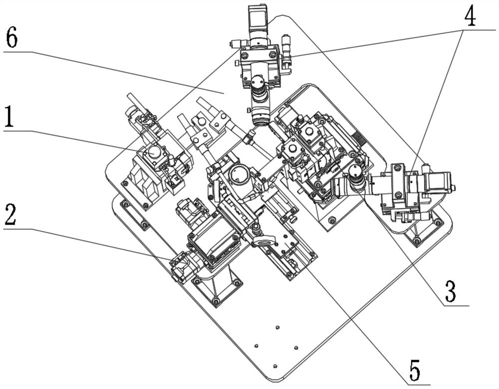
[0033] Such as figure 1 As shown, the embodiment of the present invention provides a fiber end cap automatic alignment fusion splicing device based on optical power feedback, including:

[0034] Flame injection unit 1, lower clamp unit 2, upper clamp unit 3, position monitoring unit 4, optical power detection unit 5 and installation platform 6; the upper clamp unit 3 is provided with an upper clamp motion platform and an optical fiber clamp, and the optical fiber clamp It is arranged downwards on the upper clamp moving platform, and the optical fiber clamp is used to clamp the optical fiber; the lower clamp unit 2 is provided with a lower clamp moving platform and an end cap clamp, and the end cap clamp is used to clamp the glass end cap, the end cap clamp is arranged below the optical fiber clamp through the lower clamp motion platform; the position monitoring unit 4 is provided with a first position monitoring device and a second position monitoring device, and the first pos...

Embodiment 2

[0049] Such as Figure 7 As shown, the embodiment of the present invention provides a method for automatic alignment and fusion splicing of optical fiber end caps based on optical power feedback, including:

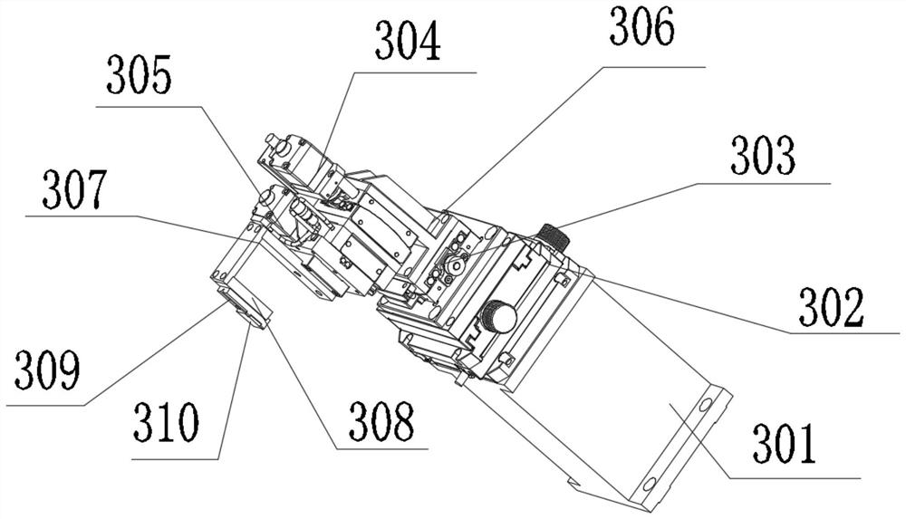
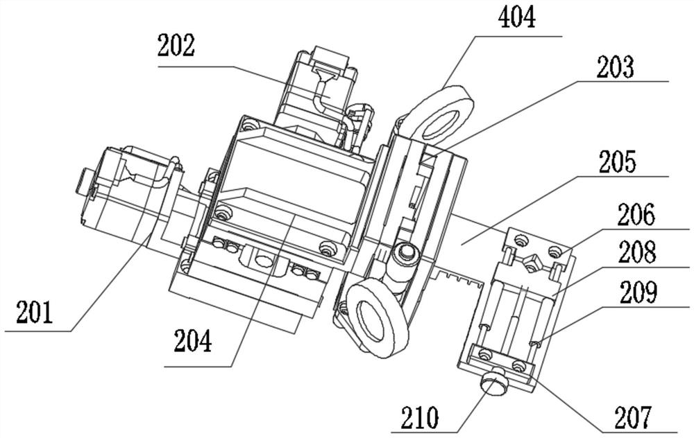
[0050] Step 1, loading the device, installing the optical fiber and the glass end cap on the optical fiber clamp and the end cap clamp respectively; the optical fiber needs to be installed in the optical fiber groove, and fixed on the optical fiber holding plate 309 by closing the optical fiber cover plate 310; the glass The end cap is installed between the clamp slider 208 and the first fixture seat 206, and the adjusting bolt 210 is rotated so that the clamping groove clamps the glass end cap; the end of the optical fiber is connected to the optical power meter;

[0051] Step 2, the optical fiber is aligned with the glass end cap, the upper fixture moving platform will drive the displacement of the optical fiber fixture through the upper fixture rotating platform 304 an...


PUM


Abstract

The invention provides an optical fiber and end cap automatic aligning and welding device based on optical power feedback. An upper clamp unit is provided with an upper clamp motion platform and an optical fiber clamp, and the optical fiber clamp is downwards arranged on the upper clamp motion platform; a lower clamp unit is provided with a lower clamp motion platform and an end cap clamp, and theend cap clamp is arranged below the optical fiber clamp through the lower clamp motion platform; a position monitoring unit is provided with a first position monitoring device and a second position monitoring device; an optical power detection unit is arranged below the end cap clamp; and a flame jetting unit is arranged beside the optical fiber clamp and the end cap clamp. The invention furtherprovides an optical fiber and end cap automatic aligning and welding method based on optical power feedback. The device is complete in structure and smooth in operation, and can realize automatic alignment and flame welding of an optical fiber and a glass end cap. Through optical power detection, the alignment precision of the optical fiber and the end cap is effectively improved, and the weldingefficiency of the optical fiber and the end cap is improved.

Description

technical field [0001] The invention relates to the technical field of optical communication, in particular to an optical fiber end cap automatic alignment fusion splicing device and method based on optical power feedback. Background technique [0002] In high-power laser fiber transmission, the core diameter of the fiber is very thin, and the high-power laser is focused into the fiber through the lens. The power density of the fiber end face is extremely high, and the fiber is easily damaged. Therefore, the fiber end face is required to be free from any damage and pollution, which is extremely demanding; The area of ​​the end face is small, and it is not easy to carry out coating treatment. There is a large loss when the laser enters the end face of the uncoated fiber, which will generate more heat that damages the fiber; the strength of the two ends of the bare fiber is low during the installation and removal process, and the clamping is very uncomfortable. Convenience and...

Claims


Application Information

Patent Timeline
IPC IPC(8): G02B6/26G02B6/25
CPCG02B6/25G02B6/262
Inventor 段吉安唐佳卢胜强罗志周海波
Owner CENT SOUTH UNIV
Why Eureka
Try Eureka