Metering pump liquid release control device of post-processing system for internal combustion engine tail gas purification

A technology for exhaust gas purification and release control, which is applied in pump control, components of pumping devices for elastic fluids, liquid variable capacity machinery, etc., to maintain metering accuracy, reduce the influence of spray-assisted air pressure, and increase practicability Effect

Active Publication Date: 2014-10-01
中村 英子 +1
View PDF4 Cites 3 Cited by
  • Summary
  • Abstract
  • Description
  • Claims
  • Application Information

AI Technical Summary

Problems solved by technology

The device adopts double liquid chamber and double valve design, one of the chambers has a variable volume. At the same time, the push rod is used to directly push the liquid release valve, and the cleaning rod is used to loosen the liquid outlet that may crystallize, which solves the contradiction between the opening and closing of the liquid release valve. , so that the metering pump can maintain good accuracy in a relatively large range of spray-assisted air pressure, and also solve a series of problems caused by the crystallization of urea solution

Method used


Image

  • Metering pump liquid release control device of post-processing system for internal combustion engine tail gas purification
  • Metering pump liquid release control device of post-processing system for internal combustion engine tail gas purification
  • Metering pump liquid release control device of post-processing system for internal combustion engine tail gas purification

Examples


Embodiment 1

[0031] The words "upper", "lower", "left", "right" etc. used in the following to describe the orientation are based on the orientation shown in the drawings for the convenience of explanation. In the actual device, these Orientation may vary due to how the unit is positioned.

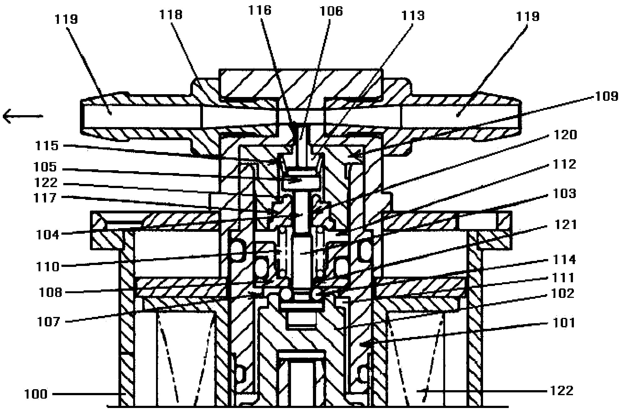
[0032] see image 3 As shown, a metering pump liquid release control device for a post-treatment system for exhaust gas purification of an internal combustion engine includes a metering pump housing 100, a metering pump cylinder 101 and a piston 102 disposed in the cylinder;

[0033] A push rod 103, a liquid release valve support rod 104, a liquid release valve 105, and a cleaning rod 106 are sequentially arranged above the piston 102; , that is, the central axes of the two coincide;

[0034] The metering pump cylinder 101 is provided with a piston running stop block 107, which is used to limit the stroke of the piston 102. When the piston 102 runs to the top, that is, it touches the piston running st...


PUM


Abstract

A metering pump liquid release control device of a post-processing system for internal combustion engine tail gas purification comprises a metering pump shell, a metering pump cylinder body and a piston arranged in the cylinder body, and a pushing stick, a liquid release valve supporting stick, a liquid release valve and a cleaning stick are sequentially arranged above the piston. A piston operation stop point baffle block is arranged in the metering pump cylinder body; a hollow sliding block and a hollow outer liquid cavity body are arranged at the position, above the piston operation stop point baffle block, in the metering pump cylinder body; a metering cavity is formed by a cylinder body space between the upper portion of the piston and the sliding block, and a temporary liquid storage cavity is formed by a space between the sliding block and the lower portion of the liquid release valve. According to the device, the influences of external spray-assisted air pressure can be greatly reduced, and the metering precision of the metering pump can be kept within the large spray-assisted air pressure range. Meanwhile, due to the design of double liquid-outlet cavities and action of the pushing stick and the cleaning stick, the metering pump is not damaged by urea crystallization, or, the normal work of the metering pump is not affected by the urea crystallization, and the practicability of the metering pump is greatly improved.

Description

technical field [0001] The invention relates to a liquid release control device for a metering pump, in particular to a liquid release control device for a metering pump in a post-treatment system for purifying exhaust gas of an internal combustion engine. Background technique [0002] At present, the urea injection system used for aftertreatment of diesel engines is mainly the air-assisted system, especially in the application of medium and heavy vehicles. The air-assisted urea injection system uses the brake compressed air on the vehicle as the air source. The usual practice is to lead the compressed air (injection aid air) to the urea metering pump, carry the urea liquid released from the metering pump to the nozzle, and finally spray it into the engine exhaust pipe. This arrangement often causes the metering of the metering pump to be disturbed and affected by the pressure of the spraying air; the main reason is that the change in the pressure outside the release valve ...

Claims


Application Information

Patent Timeline
IPC IPC(8): F04B53/00F04B49/00F04B13/00
Inventor 中村英子李平
Owner 中村 英子
Why Eureka
Try Eureka