Exhaust device for elevator furnace system

A technology of exhaust device and bell jar furnace, applied in bell jar furnace, furnace control device, furnace and other directions, can solve the problems of blockage of safety pneumatic pressure reducing valve, high temperature, affecting the overall appearance of the workshop, etc. Diffusion, the effect of solving waterproof problems

Inactive Publication Date: 2014-10-01
ZHONGDE ELECTRONICS
View PDF0 Cites 2 Cited by
  • Summary
  • Abstract
  • Description
  • Claims
  • Application Information

AI Technical Summary

Problems solved by technology

[0003] The above-mentioned design of the prior art has the following disadvantages: First, it is necessary to open a plurality of through holes in the roof, and the exhaust passages of multiple bell furnaces pass through the through holes in the roof, which affects the overall appearance of the whole factory building. At the same time, due to the exhaust High-temperature gas flows in the channel, so the temperature of the pipe wall will be high, which increases the difficulty of waterproofing the roof around the exhaust channel. Secondly, because the exhaust channel cannot be supported and reinforced on the roof, the exhaust channel protrudes from the roof. The height is affected, which is not conducive to the diffusion of exhaust gas; moreover, because the safety pneumatic pressure reducing valve is directly connected to the exhaust air passage, that is, the inlet and outlet of the safety pneumatic pressure reducing valve are connected to the exhaust air passage, while the safety pneumatic pressure reducing valve The pressure valve starts to work when the bell furnace enters the internal circulation state, so when the bell furnace is in the external circulation state, the safety pneumatic pressure reducing valve is easily blocked and fails

Method used


Image

  • Exhaust device for elevator furnace system
  • Exhaust device for elevator furnace system

Examples


Embodiment Construction

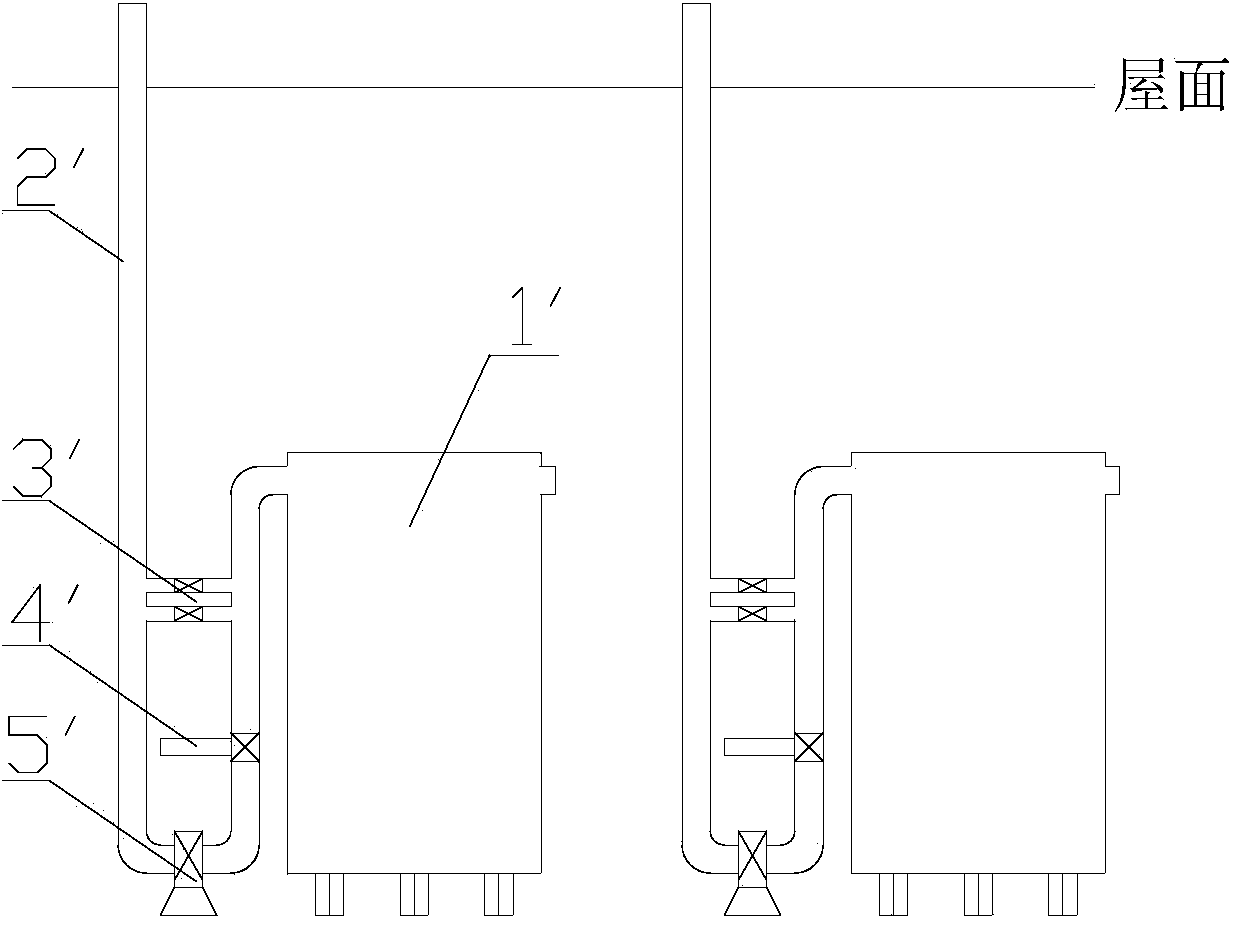
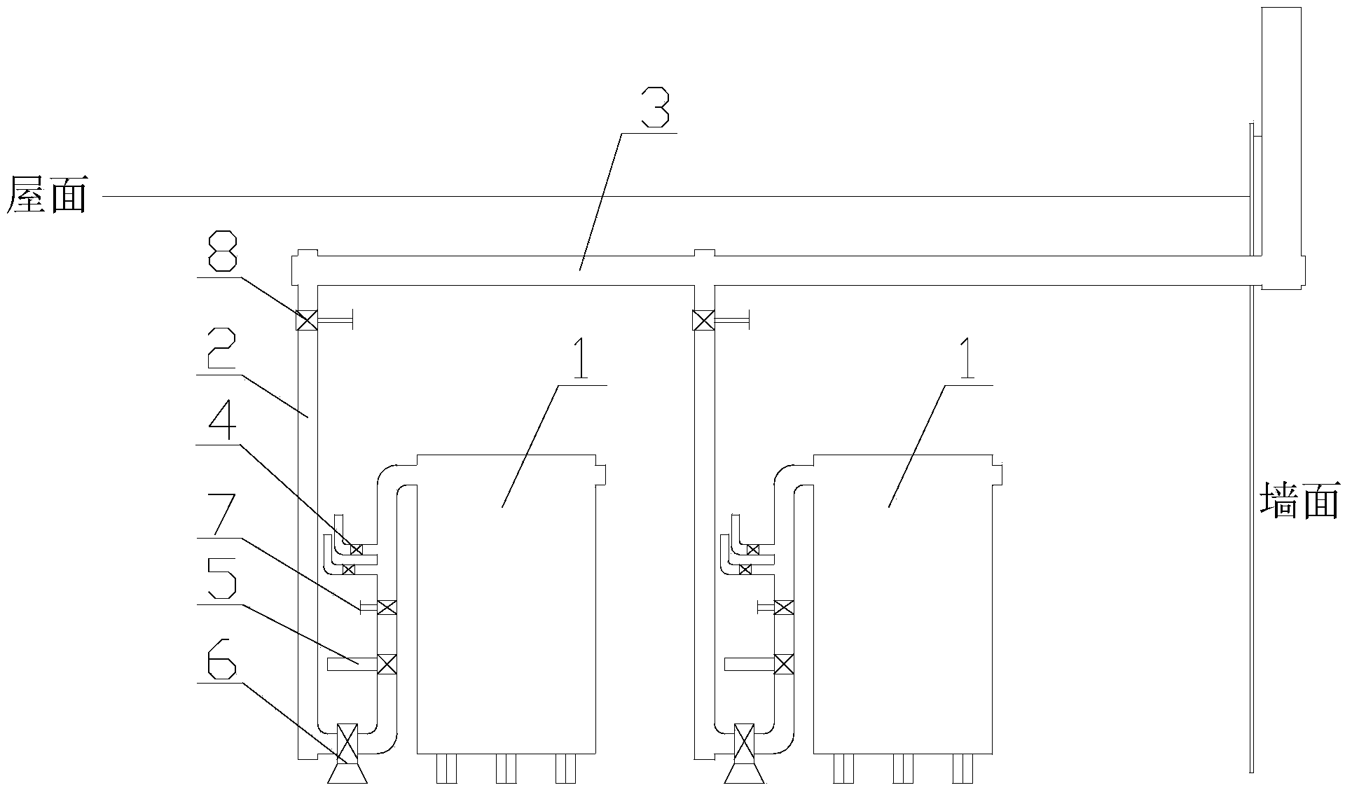
[0015] Such as figure 1 as shown, figure 1 It is a structural schematic diagram of an exhaust device of a bell furnace system proposed by the present invention.

[0016] refer to figure 1 , the exhaust device of a kind of bell jar furnace system that the present invention proposes, and described bell jar furnace system comprises M bell furnaces 1, and described exhaust device comprises M sub-row pipelines 2 and a total row pipeline 3, M The air inlets of the separate row pipes 2 are respectively connected to the gas outlets of the M bell furnaces 1, and the gas outlets of the M separate row pipes 2 are all connected to the main row pipe 3, and the general row pipe 3 passes through the wall and passes through the The fastening mechanism is fixed on the wall; along the exhaust direction from the air inlet end to the air outlet end of the distribution pipe 2, a safety pneumatic pressure reducing valve 4, an electromagnetic pneumatic valve 5 and an air exhaust valve are sequenti...


PUM


Abstract

The invention discloses an exhaust device for an elevator furnace system. The elevator furnace system comprises M elevator furnaces. The exhaust device comprises M branch exhaust pipelines and one main exhaust pipeline, wherein the air inlet ends of the M branch exhaust pipelines are connected to the air outlets of the M elevator furnaces respectively; the air outlet ends of the M branch exhaust pipelines are connected to the main exhaust pipeline respectively; the main exhaust pipeline passes through a wall surface, and is fixed on the wall surface through a fastening mechanism; along an exhaust direction from the air inlet ends of the branch exhaust pipelines to the air outlet ends, a safety pneumatic pressure-reducing valve, an electromagnetic pneumatic valve and an exhaust fan are arranged in sequence on each branch exhaust pipeline; the outlets of the safety pneumatic pressure-reducing valves are directly communicated with the outside; first manual valves are arranged on the branch exhaust pipelines of the safety pneumatic pressure-reducing valves and the electromagnetic pneumatic valves; second manual valves are arranged on the branch exhaust pipelines at the air outlet ends from the exhaust fans to the branch exhaust pipelines.

Description

technical field [0001] The invention relates to the technical field of bell furnaces, in particular to an exhaust device for a bell furnace system. Background technique [0002] Such as figure 1 As shown, in the prior art bell furnace system, it includes multiple bell furnaces, each bell furnace is provided with an independent exhaust passage, and the exhaust pipe extends out of the roof for exhaust. From the inlet to the outlet, a safety pneumatic pressure reducing valve, an electromagnetic pneumatic valve and an exhaust fan are installed in sequence. [0003] The above-mentioned design of the prior art has the following disadvantages: First, it is necessary to open a plurality of through holes in the roof, and the exhaust passages of multiple bell furnaces pass through the through holes in the roof, which affects the overall appearance of the whole factory building. At the same time, due to the exhaust High-temperature gas flows in the channel, so the temperature of the ...

Claims


Application Information

Patent Timeline
Patent Type & Authority Applications(China)
IPC IPC(8): F27B11/00F27D7/06F27D19/00
Inventor 李前军刘晶朱海林管成立
Owner ZHONGDE ELECTRONICS
Why Eureka
Try Eureka