
Temperature continuously-adjustable point-contact gas-sensitive humidity-sensitive test cavity

A gas-sensing, humidity-sensing, test chamber technology, applied in the field of gas-sensing and humidity-sensing sensor testing, can solve the problems of complex lead packaging, unable to provide a variety of temperature environments, and unable to test multiple sensitive components to be tested, etc., to achieve the internal volume Small, improve test accuracy, good sealing effect

Inactive Publication Date: 2014-10-01
UNIV OF ELECTRONICS SCI & TECH OF CHINA
View PDF14 Cites 4 Cited by
  • Summary
  • Abstract
  • Description
  • Claims
  • Application Information

AI Technical Summary

Problems solved by technology

The present invention can solve the problems existing in the existing gas-sensing and humidity-sensing test chambers that multiple sensitive components to be tested cannot be tested at the same time, various temperature environments cannot be provided, only for the application of fixed electrode size components, complex lead packaging is required before component testing, etc. question

Method used


Image

  • Temperature continuously-adjustable point-contact gas-sensitive humidity-sensitive test cavity
  • Temperature continuously-adjustable point-contact gas-sensitive humidity-sensitive test cavity
  • Temperature continuously-adjustable point-contact gas-sensitive humidity-sensitive test cavity

Examples


Embodiment 1

[0034] A temperature continuously adjustable point-contact gas-sensing and humidity-sensing test chamber is used for performance testing of gas-sensing elements or humidity-sensing elements.

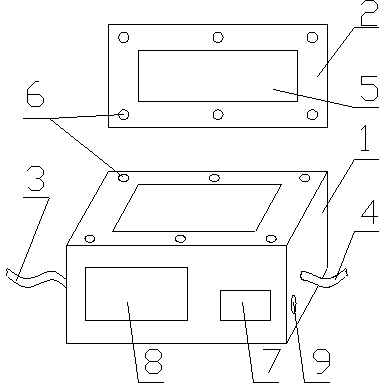
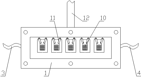
[0035]The test chamber includes a test chamber main body and a temperature control module. The main body of the test chamber includes a chamber body and a chamber cover. The chamber body and the chamber cover together form a sealed test chamber body. Both the chamber body and the chamber cover are made of polytetrafluoroethylene in the polymer material. The length of the cavity is 40mm-120mm, the width is 10mm-30mm, and the depth is 3mm-10mm. In this embodiment, the depth of the cavity inside the cavity is 3mm, the width is 10mm, and the length is 40mm. During the test, the cavity is along the length direction of the cavity. Set 4 to 6 gas sensors or humidity sensors. The cavity body and the cavity cover are correspondingly provided with threaded holes, and the cavity body and the cavit...

Embodiment 2

[0041] On the basis of Embodiment 1, the core control unit is made up of a single-chip microcomputer system, and its specific temperature control algorithm uses the existing Dahlin algorithm (the design of the entire controller of the Dahlin algorithm is based on a discrete method, and is designed in the Z domain. A suitable digital controller. The biggest feature of this algorithm is to design the expected closed-loop response of the system as an ideal first-order inertial link plus a pure lag link, and then use the expected closed-loop response transfer function and the mathematical model of the control system to find The regulator that gets the closed-loop response. The control system structure of the Dahlin algorithm is as follows: The controlled object is a first-order time-delay process: Where τ = NT, is the pure lag time. T is the sampling period, Tp is the time constant of the object, and Kp is the magnification factor. The desired closed-loop transfer function is:...

Embodiment 3

[0043] On the basis of Embodiment 1 or Embodiment 2, both the chamber body and the chamber cover are made of stainless steel among metal materials, the inner depth of the chamber body is 10 mm, the width is 30 mm, and the length is 120 mm. There are humidity sensitive elements in the cavity, and 6 humidity sensitive elements and 12 copper metal moving contacts are arranged in the cavity along the length direction of the cavity. When the material of the chamber body and the chamber cover is metal, the sealing gasket can be a corrosion-resistant flexible gasket or a rigid gasket. In this embodiment, the sealing gasket is a stainless steel gasket. The total length of the moving contact piece is 12mm, the length of the rotatable part of the moving contact piece is 10mm, and the diameter of the bump is 3mm; the distance between the moving contact piece is 15mm. The distance between the electrode connection points of the sensitive element to be tested is 10mm, and the width of the e...


PUM

PropertyMeasurementUnit
lengthaaaaaaaaaa
lengthaaaaaaaaaa
widthaaaaaaaaaa

Abstract

The invention discloses a temperature continuously-adjustable point-contact gas-sensitive humidity-sensitive test cavity, and relates to the technical field of the gas-sensitive humidity-sensitive sensor, which aims at providing a temperature continuously-adjustable point-contact gas-sensitive humidity-sensitive test cavity which is used for testing the performance of a sensitive element through toxic and corrosive gases. The temperature continuously-adjustable point-contact gas-sensitive humidity-sensitive test cavity comprises a test cavity main body and a temperature control module, wherein the test cavity main body comprises a cavity body and a cavity cover which is matched with the cavity body, the side wall of the cavity body is connected with a leading-out wire as well as a gas inlet pipe and a gas outlet pipe, wherein the gas inlet pipe and the gas outlet pipe are used for conveying the test gases, the leading-out wire is connected with a movable contact plate which is arranged in the cavity body, and when in test, a salient point of the movable contact plate is contacted with an electrode of a to-be-tested sensitive element which is arranged in the cavity body. By adopting the point contact way, the movable contact plate group is arranged in the cavity, a plurality of to-be-tested sensitive elements can be simultaneously tested, the temperature in the test cavity is continuously adjustable through the temperature control module, and the test of the to-be-tested sensitive element can be carried out in different temperature environments; moreover, the direction of the movable contact plate can be adjusted at random, so that the movable contact plate is suitable for testing the elements of different electrode sizes.

Description

technical field [0001] The invention relates to the technical field of gas- and humidity-sensitive sensor testing, in particular to a point-contact gas- and humidity-sensitive test chamber with continuously adjustable temperature. Background technique [0002] A person breathes about 15 cubic meters of air every day, and each cubic meter of air weighs about 1.3 kilograms, which is equivalent to a person needing to inhale 20 kilograms of air every day, which is more than ten times the amount of water a person drinks every day. In recent years, with the modernization of production and lifestyle, more work, entertainment, and sports activities can be carried out indoors, and people spend 80% or more of their time indoors every day on average, so indoor air quality is closely related to human life and health are closely related. [0003] According to national standards, the main parameters to evaluate indoor air quality are sulfur dioxide (SO2), nitrogen dioxide (NO2), carbon m...

Claims


Application Information

Patent Timeline
Patent Type & Authority Applications(China)
IPC IPC(8): G01N33/00
Inventor 太惠玲刘春华蒋亚东徐晓颖谢光忠杜晓松
Owner UNIV OF ELECTRONICS SCI & TECH OF CHINA
Learn More