
Compensating inductor energy storage generator

A technology of inductors and generators, applied in the direction of electromechanical devices, electrical components, electric components, etc., can solve the problems of large inductance, limit the rising speed and peak value of discharge current, achieve the ability of reducing inductance and improving instantaneous output power Effect

Inactive Publication Date: 2014-10-01
HUAZHONG UNIV OF SCI & TECH
View PDF4 Cites 0 Cited by
  • Summary
  • Abstract
  • Description
  • Claims
  • Application Information

AI Technical Summary

Problems solved by technology

When the traditional alternator is discharging, the armature reaction magnetic field passes through the air gap and closes the rotor, that is, the stator flux links with the rotor through the air gap, so that the equivalent transient internal inductance of the generator is relatively large, which limits the discharge. Rising speed and peak value of current

Method used


Image

  • Compensating inductor energy storage generator
  • Compensating inductor energy storage generator

Examples


Embodiment Construction

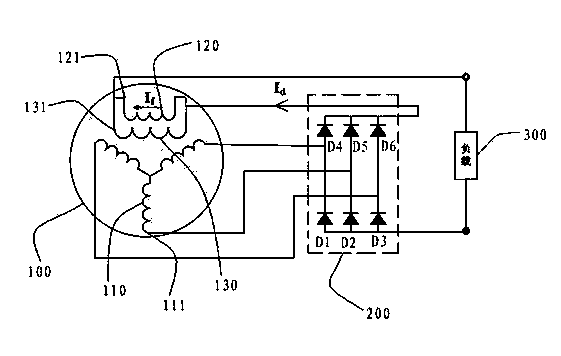
[0013] see figure 1 , in a preferred embodiment of the present invention, a compensated induction sub-energy storage generator includes a motor unit 100 , a rectifier circuit 200 and a load 300 .

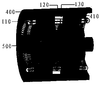
[0014] The motor unit 100 includes an armature winding 110 , an excitation winding 120 and a compensation winding 130 . The armature winding 110 includes a plurality of first connecting ends 111 . The excitation winding 120 includes a plurality of second connection ends 121 . The compensation winding 130 includes a plurality of third connection ends 131 .

[0015] The rectifier circuit 200 includes a first diode D1, a second diode D2, a third diode D3, a fourth diode D4, a fifth diode D5 and a sixth second diode Pole tube D6. Anodes of the first diode D1 , the second diode D2 and the third diode D3 are respectively electrically connected to the anode of the load 300 . The cathodes of the first diode D1, the second diode D2 and the third diode D3 are electrically connected to th...


PUM


Abstract

A compensating inductor energy storage generator comprises a motor unit and a rectifying circuit. The motor unit comprises an armature winding, an exciting winding and a compensating winding. The rectifying circuit comprises a plurality of diodes. The armature winding is electrically connected with the compensating winding and a load through the diodes, and the exciting winding is connected to the two ends of the compensating winding in parallel. When the motor unit carries out instantaneous discharge on the load, the compensating winding provides compensating currents, so that a varying magnetic field is generated and interacts with a reaction magnetic field of the armature winding, equivalent instantaneous internal inductance of the motor unit is reduced, and the capacity of the motor unit for outputting power instantaneously is improved.

Description

[0001] technical field [0002] The invention relates to an induction sub-energy storage generator, in particular to a compensation type induction sub-energy storage generator. Background technique [0003] The pulse power output capability of a traditional alternator has a great relationship with the no-load voltage and internal impedance of the generator. When the pulse power is output, the working state of the generator is similar to an instantaneous short circuit. At this time, the pulse current output by the generator is directly related to its internal impedance, that is, the transient internal inductance. The smaller the transient internal inductance of the generator, the stronger its ability to output pulse power. When the traditional alternator is discharging, the armature reaction magnetic field passes through the air gap and closes the rotor, that is, the stator flux links with the rotor through the air gap, so that the equivalent transient internal inductance of...

Claims


Application Information

Patent Timeline
Patent Type & Authority Applications(China)
IPC IPC(8): H02K11/00
Inventor 于克训马志源潘垣韦忠朝叶才勇
Owner HUAZHONG UNIV OF SCI & TECH
Learn More