Visual multifunctional pilot scale test synthesis device

A synthetic equipment and multi-functional technology, applied in chemical instruments and methods, chemical/physical processes, chemical/physical/physical chemical processes, etc., can solve problems that cannot be reflected intuitively, achieve intuitive viewing, improve students' hands-on ability, Awareness-enhancing effects

Inactive Publication Date: 2014-10-08
李健 +1
View PDF8 Cites 0 Cited by
  • Summary
  • Abstract
  • Description
  • Claims
  • Application Information

AI Technical Summary

Problems solved by technology

[0007] Aiming at the problems existing in the current teaching, and the problem that the pilot test stage cannot directly reflect the changes in various links after the experiment is expanded, a visual multifunctional pilot test synthesis equipment is provided, including a reactor. Body, upper cover, and a heat-conducting oil accommodation cavity formed outside the reactor body. The upper cover of the reactor is provided with a feed hole and an observation hole for observation. The lower end of the reactor is provided with a discharge A stirrer and a temperature detection device are also installed in the reactor; a heat-conducting oil furnace is also provided, and a high-transparency heat-conducting oil is installed in the heat-conducting oil furnace, and the heat-conducting oil furnace and the heat-conducting oil on the outside of the reactor body The accommodating cavities are communicated through heat conduction oil pipelines; it also includes a high-transparency glass high-level feed tank, and the high-transparency glass high-level feed tank communicates with the feed hole of the reaction kettle through feed pipes; it also includes a high-transparency glass high-level feed tank. Glass condensing reflux device; the upper cover of the reaction kettle is provided with air holes, and the air inlet end of the high-transparency glass condensing reflux device communicates with the air holes of the reaction kettle through gas pipelines; control valves are arranged on the various pipelines

Method used


Image

  • Visual multifunctional pilot scale test synthesis device
  • Visual multifunctional pilot scale test synthesis device
  • Visual multifunctional pilot scale test synthesis device

Examples


Embodiment 1

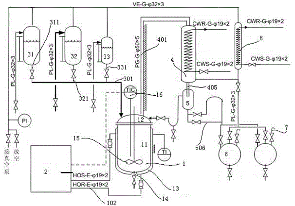
[0042] Such as figure 1 As shown, the salt-forming acidification equipment includes: a reaction kettle 1, the reaction kettle includes a kettle body 11, an upper cover 12, and a heat-conducting oil accommodating cavity 13 formed on the outside of the kettle body, and the reaction kettle upper cover 12 is provided with There is a feed hole and an observation hole for observation. The lower end of the reaction kettle 1 is provided with a discharge port 14. A stirrer 15 and a temperature display control device 16 are also installed in the reaction kettle; it also includes a heat transfer oil. Furnace 2, the heat-conducting oil furnace 2 is equipped with high-transparency heat-conducting oil, and the heat-conducting oil furnace communicates with the heat-conducting oil chamber outside the reactor body through a heat-conducting oil pipeline 102; it also includes a high-transparency glass high-level Feed tank, the high-level feed tank of high transparency glass includes a high-level...

Embodiment 2

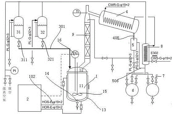
[0048] Such as figure 2 As shown, the rectification equipment includes: a reaction kettle 1, the reaction kettle includes a kettle body 11, an upper cover 12, and a heat-conducting oil accommodating cavity 13 formed on the outside of the kettle body, and the reaction kettle upper cover 12 is provided with Feed hole, the lower end of the reaction kettle 1 is provided with a discharge port 14, and a stirrer 15 and a temperature display control device 16 are also installed in the reaction kettle. Here, the reaction kettle is more accurately called a solvent rectification kettle. It also includes a heat-conducting oil furnace 2, which is equipped with a high-transparency heat-conducting oil, and is communicated with the heat-conducting oil accommodating cavity on the outside of the reactor body through a heat-conducting oil pipeline 102; Including a high-level feed tank of high-transparency glass, the high-level feed tank of high-transparency glass includes a high-level feed tank...

Embodiment 3

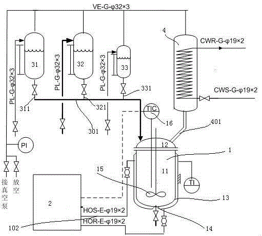
[0055] Such as image 3 As shown, the acylation equipment includes: a reaction kettle 1, the reaction kettle includes a kettle body 11, an upper cover 12, and a heat transfer oil accommodating cavity 13 formed on the outside of the kettle body, and the reaction kettle upper cover 12 is provided with a There is a feed hole, the lower end of the reactor 1 is provided with a discharge port 14, and an agitator 15 and a temperature display control device 16 are also installed in the reactor. In this embodiment, the reactor should be understood as an acylation reaction Kettle; also includes a heat-conducting oil furnace 2, the heat-conducting oil furnace 2 is equipped with high-transparency heat-conducting oil, and the heat-conducting oil furnace is communicated with the heat-conducting oil accommodating cavity outside the reactor body through a heat-conducting oil pipeline 102; It also includes a high-level feed tank of high-transparency glass. The high-level feed tank of high-tran...


PUM


Abstract

The invention relates to a synthesis device and more specifically relates to a visual multifunctional pilot scale test synthesis device. In order to solve the problems in the current teaching and the problem of incapability of visually reflecting the change of all processes after expanding the test in the pilot scale test stage, the visual multifunctional pilot scale test synthesis device is provided. The visual multifunctional pilot scale test synthesis device comprises a reaction kettle, a heat conduction oil furnace, a high-transparency glass high-position feeding tank and a high-transparency glass condensate returning device, wherein the heat conduction oil furnace is filled with high-transparency heat conduction oil; the heat conduction oil furnace is communicated with a heat conduction oil storage cavity on the outer side of a reaction kettle body through a heat conduction oil pipeline; the high-transparency glass high-position feeding tank is respectively communicated with feeding holes of the reaction kettle through a feeding pipeline. By virtue of the visual multifunctional pilot scale test synthesis device, the practical abilities of students can be improved and the engineering consciousnesses of the students can be cultivated; moreover, the visual multifunctional pilot scale test synthesis device can be applied to actual production and practice and also can provide relatively intuitive and accurate guidance for expanding laboratory data to industrial production.

Description

technical field [0001] The present invention relates to a synthesis equipment, in particular to a chemical synthesis equipment, more specifically to a visualized multifunctional pilot scale synthesis equipment. [0002] Background technique [0003] At present, most schools are only equipped with experimental instruments for laboratories. However, due to the great difference between laboratory experiments and industrial production, students cannot seamlessly integrate with industrial production after graduation. [0004] Although in order to overcome this problem, qualified schools will arrange factory internships and other links, but since industrialized production processes generally use metal industrial equipment, students cannot see the reactions and changes that occur in each link during the internship. [0005] At the same time, we found that the current pilot experiment can only provide a certain data reference between the experiment in the laboratory and the industr...

Claims


Application Information

Patent Timeline
Patent Type & Authority Applications(China)
IPC IPC(8): B01J19/00B01J19/18
Inventor 陆国飞李健薛蒙伟
Owner 李健
Why Eureka
Try Eureka