Al technical title is built by PatSnap Al team. It summarizes the technical point description of the patent document.
A pipe cutter, fast technology, applied in metal processing and other directions, can solve the problems of low incision straightness, low production efficiency, inconvenient movement, etc.
Active Publication Date: 2014-10-08
FUJIAN SPIRITFOG ENVIRONMENT SCI & TECH CO LTD
View PDF8 Cites 15 Cited by
Summary
Abstract
Description
Claims
Application Information
AI Technical Summary
This helps you quickly interpret patents by identifying the three key elements:
Problems solved by technology
Method used
Benefits of technology
Problems solved by technology
The straightness and stability of the operator's hand push directly affect the straightness of the pipe cutting incision. The straightness of the pipe cutting in this way is low, and the production efficiency is also low.
Moreover, the structure layout of the existing pipe cutting machine is not reasonable enough, the volume is relatively large, and it is inconvenient to move
Method used
Image
Click on the blue label to locate the original text in one second.
Reading with bidirectional positioning of images and text.
Examples
Embodiment Construction
[0046] In order to further explain the technical solution of the present invention, it will be described in detail below in conjunction with the accompanying drawings.
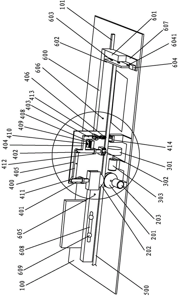
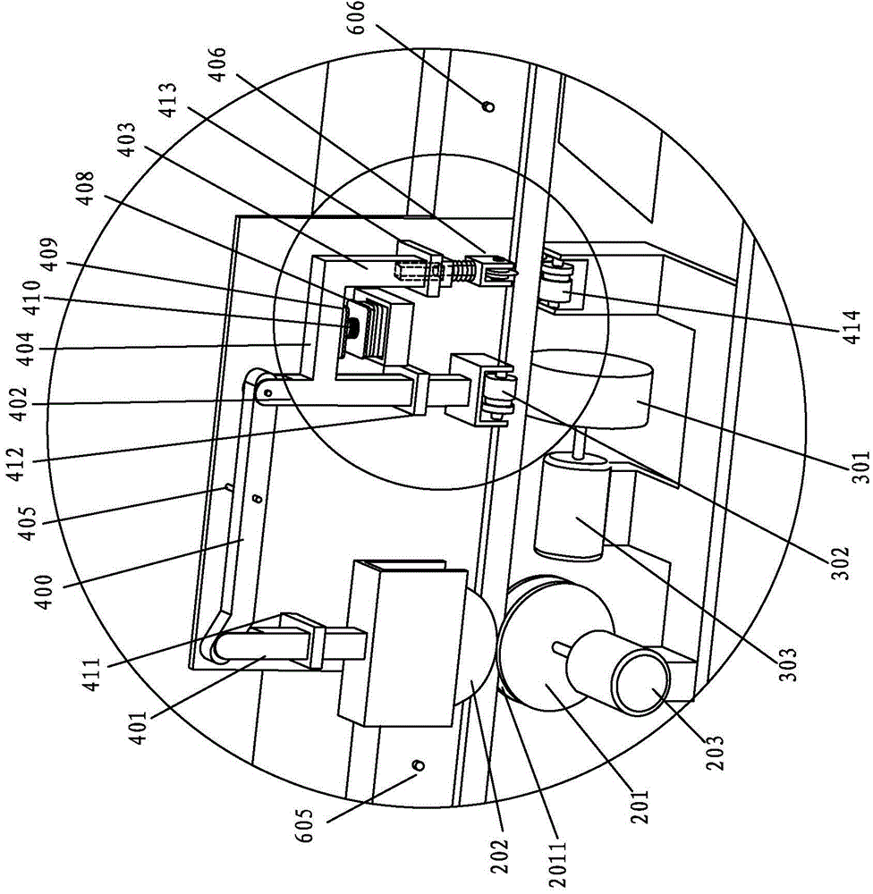
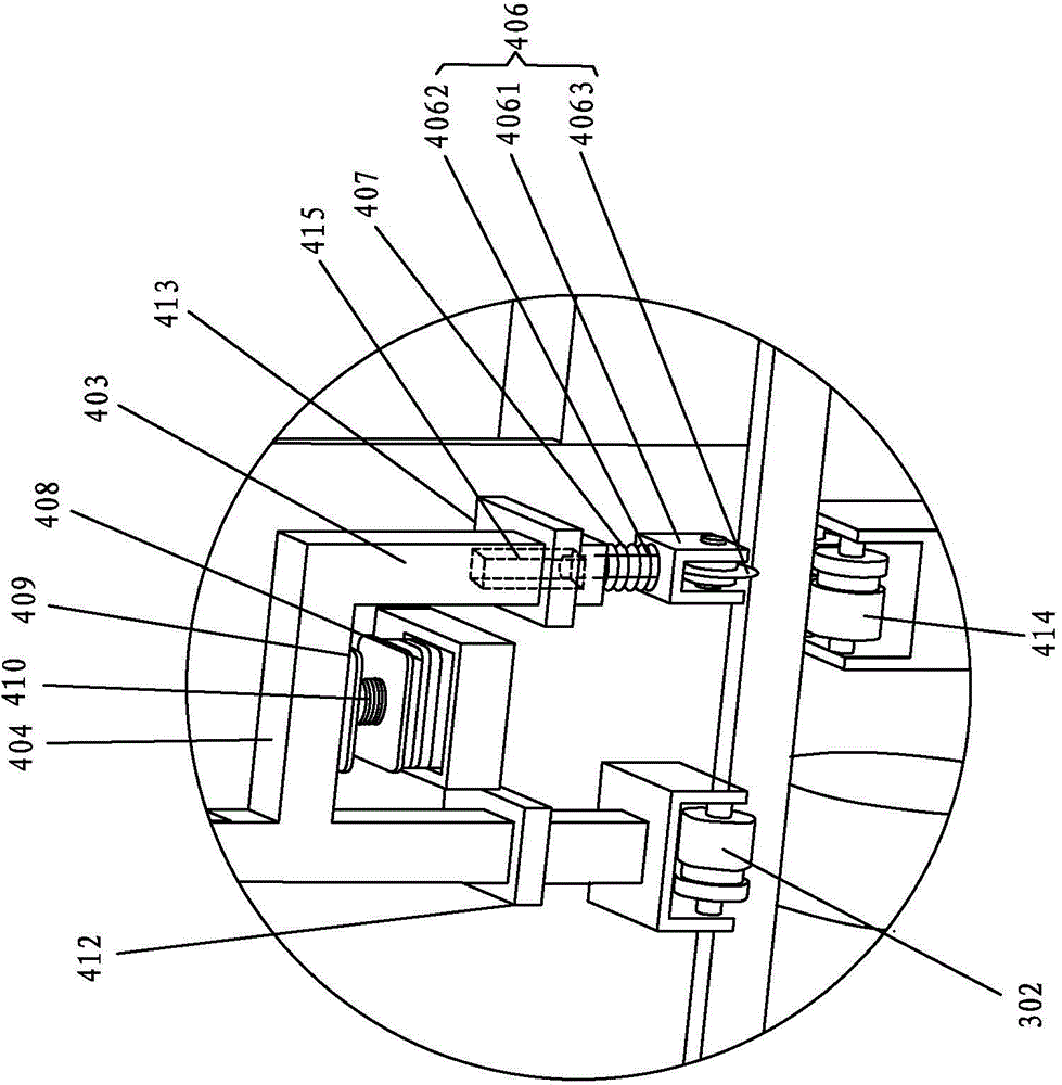
[0047] Such as Figures 1 to 3 As shown, a quick pipe cutter includes a frame 100, a pipe conveying mechanism, a pipe clamping synchronous rotation mechanism, a knife holder 406 for cutting pipes, and a control system (not shown in the figure). The shape of the frame 100 can be set according to the parts in the frame 100, which mainly supports and fixes the parts, and at the same time makes the parts closely and orderly form a whole. Taking the advancing direction of the pipe 500 as the front, the pipe conveying mechanism is used to push the pipe 500 forward along its axis, and the pipe clamping synchronous rotation mechanism is used to drive the pipe 500 to rotate around its axis. The control system integrates the circuits of each component into a unified control box for control, for example, a PLC control s...
PUM
Abstract
The invention belongs to the field of tube cutting equipment, and particularly relates to a rapid tube cutter. The rapid tube cutter comprises a rack, a tube conveying mechanism, a tube clamping synchronous rotation mechanism, a cutter rest, a control system, a linkage rod, a hinge shaft, a first support arm, a second support arm, a third support arm, an electromagnet, an attraction component, an adjustment arm, a limit plate, a stroke switch, a first elastic component, a second elastic component, a third elastic component, a first infrared probe and a second infrared probe. With the adoption of the technical scheme of the invention, the cutting length of a tube is determined by presetting the distance between the limit plate and a blade assembly, thus reducing the errors due to visual assessment; meanwhile, the matching of a first motor, a second motor, the electromagnet and the stroke switch is realized by the control system, and automatic cutting for the tube can be realized only by placing the tube on a support wheel; compared with manual tube cutting, the rapid tube cutter disclosed by the invention is high in working efficiency; moreover, the tube cutter is compact in structure, relatively small in size, and convenient to move.
Description
technical field [0001] The invention belongs to the field of pipe material cutting equipment, and in particular relates to a quick pipe cutter. Background technique [0002] At present, ordinary pipe cutting machines generally use the following methods to cut pipes: 1. Manually feed materials, and use a ruler to determine the cutting length of pipe fittings. Due to the manual feeding, the operator visually measures the length with his eyes. Due to the different viewing angles, the error in determining the length is relatively large, and it is time-consuming and labor-intensive. 2. Fix the grinding wheel cutting machine assembly, and the operator pushes the pipe fittings to cut off. The straightness and stability of the operator's hand push directly affect the straightness of the incision of the pipe cutting. In this way, the straightness of the pipe cutting incision is low, and the production efficiency is also low. Moreover, the existing pipe cutting machine structure lay...
Claims
Application Information
Patent Timeline
Application Date:The date an application was filed.
Publication Date:The date a patent or application was officially published.
First Publication Date:The earliest publication date of a patent with the same application number.
Issue Date:Publication date of the patent grant document.
PCT Entry Date:The Entry date of PCT National Phase.
Estimated Expiry Date:The statutory expiry date of a patent right according to the Patent Law, and it is the longest term of protection that the patent right can achieve without the termination of the patent right due to other reasons(Term extension factor has been taken into account ).
Invalid Date:Actual expiry date is based on effective date or publication date of legal transaction data of invalid patent.
Patent Type & Authority Applications(China)
IPC IPC(8): B26D1/16B26D7/28B26D7/02
Inventor 邓金荣陈振斌
Owner FUJIAN SPIRITFOG ENVIRONMENT SCI & TECH CO LTD