Commutator production special equipment

A special equipment and commutator technology, applied in the direction of coating, etc., can solve the problems of high labor intensity, large man-hour consumption, and low production efficiency, and achieve the effects of simple structure, improved production efficiency, and optimized schedule

Active Publication Date: 2016-06-29
ANGU GRP CO LTD
View PDF5 Cites 0 Cited by
  • Summary
  • Abstract
  • Description
  • Claims
  • Application Information

AI Technical Summary

Problems solved by technology

[0002] In the commutator production process, there is a very important process called commutator injection molding process. The commutator injection molding process is to complete the combination of commutator copper feet and plastic through plastic injection. There are many related auxiliary processes, such as sending the commutator copper feet into the mold barrel before injection molding, demolding the commutator after injection molding, and removing the commutator product from the mold barrel and the rest of the material chamber after injection molding. Cleaning of the remaining plastic, etc., all of the above-mentioned operations will consume a lot of man-hours, the operation is complicated and loose, the production efficiency is low, and the labor intensity of the workers is high.

Method used


Image

  • Commutator production special equipment
  • Commutator production special equipment
  • Commutator production special equipment

Examples


Embodiment Construction

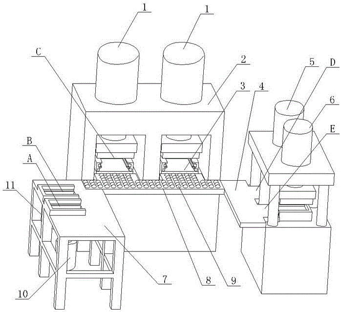
[0017] like figure 1 As shown, the special equipment for commutator production of the present invention includes commutator production stations arranged in a semi-enclosed shape, two injection molding stations C arranged side by side in the middle of the semi-enclosed shape, and side by side on the left side of the semi-enclosed shape. The demoulding station A and material chamber cleaning station B are set, the mold barrel feeding station D and the mold barrel discharging station E are arranged side by side on the right side of the semi-enclosed shape, and the two injection molding stations C correspond to a double Station press 2 and two sets of injection molds, demoulding station A corresponds to a set of demoulding molds, material chamber cleaning station B corresponds to a set of material chamber cleaning molds, the demoulding mold and material chamber cleaning molds are on the left workbench 7 Installed on top, barrel feeding station D corresponds to a set of barrel feed...


PUM


Abstract

The invention discloses a device specialized for manufacturing a commutator. The device is characterized by comprising a commutator manufacturing position arranged in a semi-encircled shape; the middle of the semi-encircled shape is two injection molding positions arranged side by side; the left side of the semi-encircled shape is a demolding position and a material chamber cleaning position; the right side of the semi-encircled shape is a mold barrel feeding position and a mold barrel discharging position which are arranged side by side; the two injection molding positions correspond to one double-position pressing machine and two injection molding molds; the demolding position corresponds to one demolding mold; the material chamber cleaning position corresponds to one material chamber cleaning mold; the demolding mold and the material chamber cleaning mold are installed on a left working table; the mold barrel feeding position corresponds to one mold barrel feeding mold; the mold barrel discharging position corresponds to one mold barrel discharging mold; and the mold barrel feeding mold and the mold barrel discharging mold are installed on a right working table. The device is used for injection molding and relevant processes before and after the injection molding during a manufacturing process of the commutator, simplifies and integrates the whole operation, and increases production efficiency.

Description

technical field [0001] The invention relates to the technical field of commutators, in particular to a special equipment for making commutators. Background technique [0002] In the commutator production process, there is a very important process called commutator injection molding process. The commutator injection molding process is to complete the combination of commutator copper feet and plastic through plastic injection. There are many related auxiliary processes, such as sending the commutator copper feet into the mold barrel before injection molding, demolding the commutator after injection molding, and removing the commutator product from the mold barrel and the rest of the material chamber after injection molding. The cleaning etc. of staying plastic, above-mentioned all these operations all will consume a large amount of man-hours, and operation seems complicated and loose, and production efficiency is low, and workman's labor intensity is big. Contents of the inv...

Claims


Application Information

Patent Timeline
Patent Type & Authority Patents(China)
IPC IPC(8): B29C45/14B29C45/26B29C45/40B29C45/17
CPCB29C45/14B29C45/26B29C45/40
Inventor 陈辉陈林郑道武陈炜炜周新喆阮志清周晓军
Owner ANGU GRP CO LTD
Why Eureka
Try Eureka