Inserting-connection assembly for automobile seat headrest
A technology for car seats and headrests, which is applied to vehicle seats, vehicle parts, special positions of vehicles, etc., can solve problems such as easy circumferential rotation, and achieve the effects of increased pressure, good structural stability, and tight fit
- Summary
- Abstract
- Description
- Claims
- Application Information
AI Technical Summary
Problems solved by technology
Method used
Image
Examples
Embodiment 1
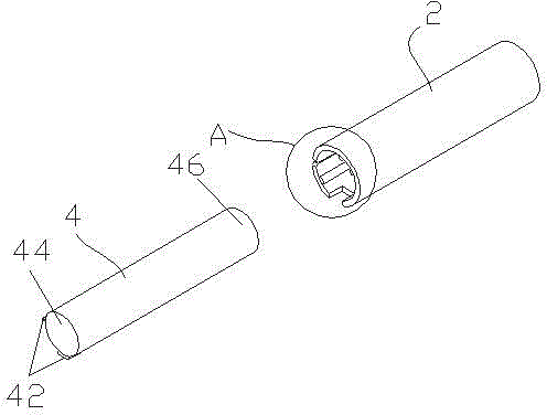
[0026] Such as Figure 1-2 As shown, a plug-in assembly of a car seat headrest includes an insertion tube 2 and an insertion rod 4 inserted in the insertion tube 2 and whose shape matches the inner shape of the insertion tube 2 . The insertion rod 4 is used to be connected with the headrest, and the insertion tube 2 is used to be fixed on the interior floor of the automobile.
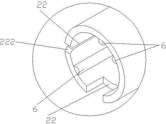
[0027] The intubation tube 2 is a round tube, hollow and open at one end. The opening end of the intubation tube 2 is provided with two circumferentially distributed grooves 22 , and the insertion rod 4 is provided with two protrusions 42 respectively matched with the two grooves 22 . Specifically, the two ends of the insertion rod 4 are respectively a head 44 and a tail 46 , and the protrusion 42 is arranged on the head 44 . The two grooves 22 form an angle of 90° at the circumferential position of the cannula 2 . More specifically, the groove walls on both sides of the opening end of the groove 22 a...
Embodiment 2
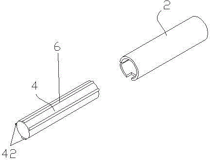
[0031] Such as image 3 As shown, a plug-in assembly of a car seat headrest differs from Embodiment 1 in that the rib 6 is arranged on the outer wall of the plug-in rod 4 . When the insertion rod 4 is inserted into the intubation tube 2 , the rib 6 of the insertion rod 4 just abuts against the inner wall of the intubation tube 2 .
Embodiment 3
[0033] Such as Figure 4-5 As shown, a plug-in assembly of a car seat headrest differs from Embodiment 1 in that: the insertion tube 2 is also provided with a number of adjustment holes 8 distributed axially discretely, and the insertion tube 2 can be fixed to the insertion tube by clamping. Any adjustment hole 8 position of the pipe 2. In addition, two ribs 6 are circumferentially distributed on the inner wall of the cannula 2 . The protrusion 42 is arranged on the tail 46 of the insertion rod 4 , and the depth of the groove 22 covers all the adjusting holes 8 distributed in the axial direction.
[0034] Specifically, the intubation tube 2 is provided with two groups of adjustment holes facing each other in the circumferential direction, and each group is composed of a single adjustment hole 8 arranged in the axial direction, that is, the two groups of adjustment holes 8 correspond one-to-one, and the corresponding two adjustment holes 8 are circumferentially aligned. Relat...
PUM
 Abstract
Description
Claims
Application Information
 - R&D
- Intellectual Property
- Life Sciences
- Materials
- Tech Scout
- Unparalleled Data Quality
- Higher Quality Content
- 60% Fewer Hallucinations
Browse by: Latest US Patents, China's latest patents, Technical Efficacy Thesaurus, Application Domain, Technology Topic, Popular Technical Reports.
© 2025 PatSnap. All rights reserved.Legal|Privacy policy|Modern Slavery Act Transparency Statement|Sitemap|About US| Contact US: help@patsnap.com


