
Method and system for preparing sponge iron by using gas-based shaft furnace

A gas-based shaft furnace and sponge iron technology, applied in the field of metallurgy, can solve the problems that the sensible heat of the sponge iron is not utilized, the reducing gas is difficult to reach the center of the shaft furnace, and the energy consumption is high.

Active Publication Date: 2014-10-08
SHENWU TECH GRP CO LTD
View PDF5 Cites 11 Cited by
  • Summary
  • Abstract
  • Description
  • Claims
  • Application Information

AI Technical Summary

Problems solved by technology

There are four problems in this method: (1) Since the reducing gas enters the shaft furnace from the bottom of the reducing section, and the sensible heat of the sponge iron is not utilized, the reducing gas heating equipment has a large scale and high energy consumption
(2) The reducing gas enters the shaft furnace from the surrounding tube at the bottom of the reduction section, and it is difficult for the reducing gas to reach the center of the shaft furnace, and the distribution of the reducing gas flow is uneven
(4) Due to the H in the circulating cooling gas 2 / The value of carbon monoxide is relatively high, the content of carbon monoxide in the gas is relatively low, and the carburizing effect of sponge iron is not very ideal

Method used


Image

  • Method and system for preparing sponge iron by using gas-based shaft furnace
  • Method and system for preparing sponge iron by using gas-based shaft furnace

Examples


Embodiment

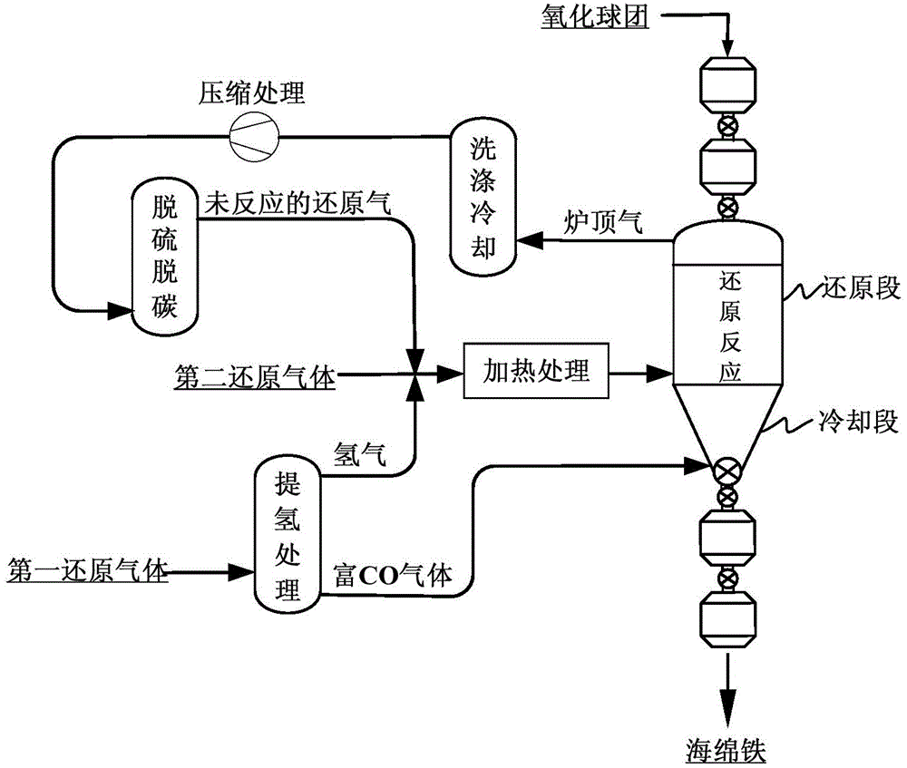
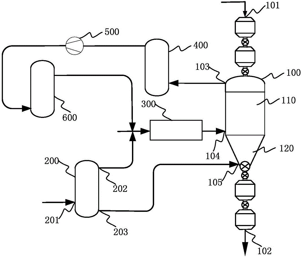
[0062] Such as figure 1 with figure 2As shown, the fresh reducing gas is divided into two parts, one part passes through the gas hydrogen extraction device, and this part of the gas is divided into hydrogen and carbon monoxide-rich gas, and the hydrogen and the other part of the fresh reducing gas are passed into the gas heating furnace for heating to 900-1000 degrees Celsius, and then enter the shaft furnace reduction section from the surrounding pipe at the bottom of the shaft furnace reduction section to carry out reduction reaction with the oxidized pellets entering from the upper part of the shaft furnace. The carbon monoxide-rich gas passes into the bottom of the cooling section of the shaft furnace to exchange heat with the hot sponge iron, and cools the sponge iron to below 50°C in the cooling section of the shaft furnace, while the carburizing reaction consumes part of the carbon monoxide. This part of the carbon monoxide-rich gas is heated to 850-900 degrees Celsiu...


PUM


Abstract

The invention discloses a method for preparing sponge iron by using a gas-based shaft furnace. The method comprises the following steps of (1) adding an oxidized pellet into the gas-based shaft furnace, wherein the gas-based shaft furnace is provided with a reducing section and a cooling section; (2) carrying out hydrogen extraction treatment on first reducing gas to obtain hydrogen and carbon monoxide enriched gas; (3) mixing second reducing gas and hydrogen, and carrying out heat treatment to obtain heat-state reducing gas; (4) delivering the heat-state reducing gas into the reducing section, and enabling the heat-state reducing gas and the oxidized pellet to be subjected to reduction reaction to obtain sponge iron and top gas; (5) delivering the carbon monoxide enriched gas into the cooling section to ensure that the carbon monoxide enriched gas upwards enters the reducing section after being subjected to heat exchange and carburization reaction with the sponge iron in the cooling section; (6) sequentially and respectively carrying out washing and cooling treatment, compression treatment as well as desulfuration and decarburization treatment on the top gas to obtain unreacted reducing gas; and (7) mixing the unreacted reducing gas and the second reducing gas. By using the method, the energy consumption of a direct reducing process of the gas-based shaft furnace can be effectively reduced.

Description

technical field [0001] The invention relates to the technical field of metallurgy, in particular, the invention relates to a method for preparing sponge iron in a gas-based shaft furnace. Background technique [0002] Sponge iron is a steelmaking raw material that replaces steel scrap and is superior to steel scrap. It can dilute the impurity elements in steel scrap, provide essential pure iron raw materials for electric furnace steelmaking, and provide high-quality billet castings for important products produced by high-end equipment manufacturing enterprises. An important raw material for the development of equipment manufacturing industry. [0003] At present, more than 75% of the sponge iron in the world is produced by the gas-based shaft furnace method, and the typical processes are MIDREX process, HYLⅢ (Energiron) process and PERED process. There are two ways to discharge sponge iron, hot discharge to produce hot briquette (HBI) and hot sponge iron (HDRI), and cold di...

Claims


Application Information

Patent Timeline
IPC IPC(8): C21B13/02C21B13/14
Inventor 吴道洪张奔李志远
Owner SHENWU TECH GRP CO LTD
Learn More