

Rotating type plant wall body suitable for multi-story or high-rise buildings
A high-rise building, rotating technology, applied in the direction of building structure, building, building components, etc., can solve the problems of the impact of the scope of application, airtightness, safety can not meet the requirements of building exterior walls, can not be used for building exterior walls, etc. To achieve the effect of meeting the ventilation needs
- Summary
- Abstract
- Description
- Claims
- Application Information
AI Technical Summary
Problems solved by technology
Method used
Image

Examples
Embodiment 1
[0038] Example 1. Working process of rotating plant wall
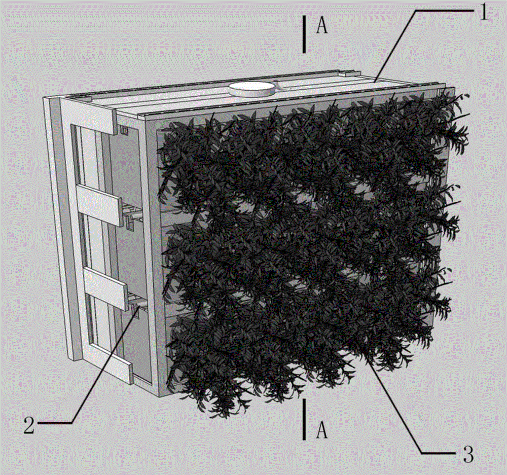
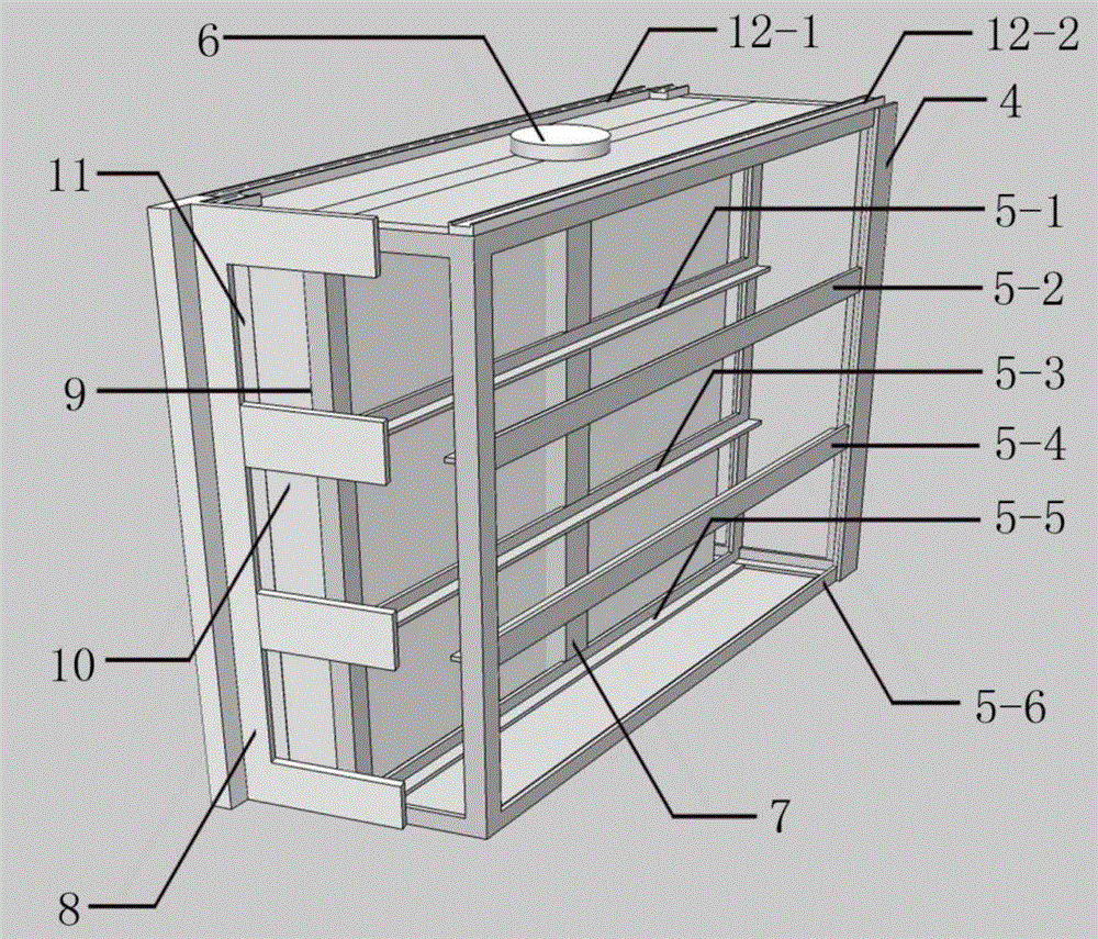
[0039] In this embodiment, the overall size of each frame unit 1 of the rotary plant wall is 750 mm long, 600 mm high, and 250 mm thick, and three supporting guide wheel chutes 15 are arranged in the height direction to place three boxed plants with a height of 180 mm. Drawer unit 3, its frame unit 1 rotates and works as follows Figure 11 , Figure 12 As shown, the work flow of building ventilation and plant replacement is as follows Figure 13 , Figure 14 , Figure 15 , Figure 16 shown;
[0040] When the wall is closed, its state is as follows Figure 11 , Figure 13 As shown, the outer facades between the left and right adjacent frame units 1 rely on the strip cover plate welded to the edge of the outer wall of the angle steel frame 4 to close the outer facades of the splicing space, while the inner facades rely on T-shaped latch locks 8 to seal. Closed so that the entire wall forms a continuous flat surfa...
Embodiment 2
[0043] Example 2. Rotating vegetal wall used as window element
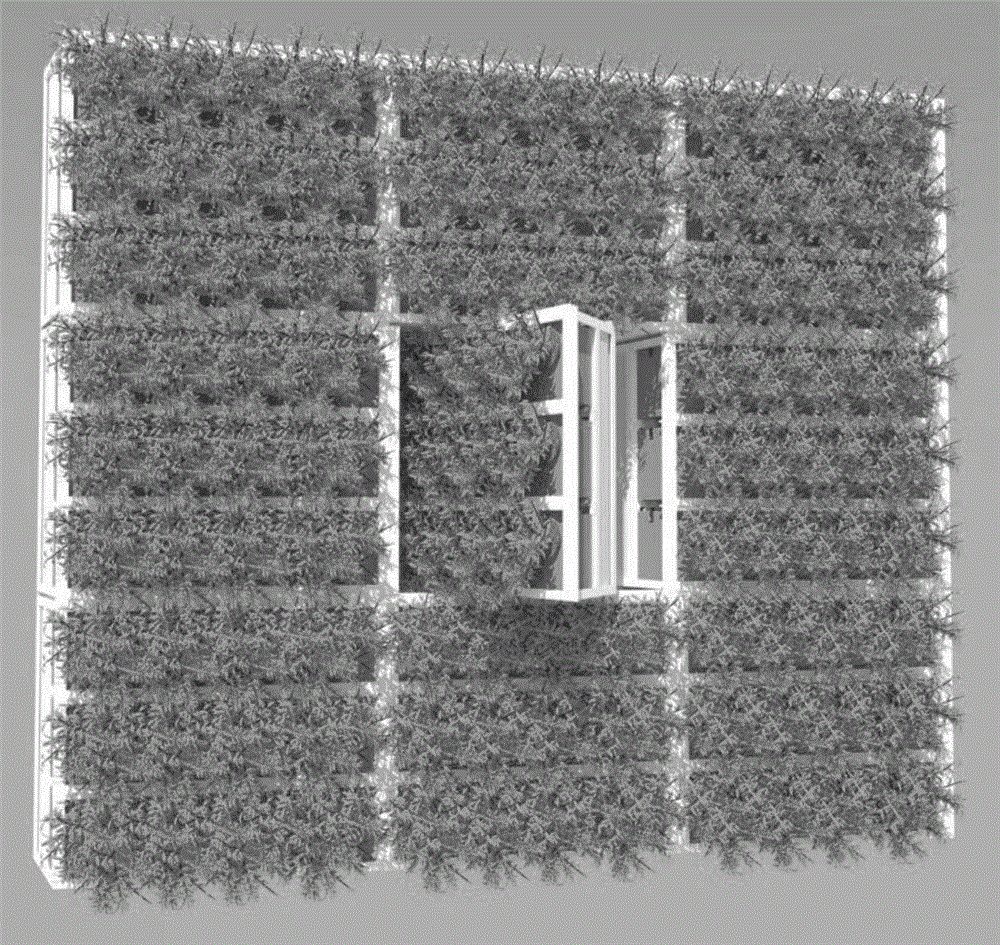
[0044] According to different arrangements of the interior space of the building, the rotating plant wall can replace some of its components inside the frame unit 1 to form windows required for lighting and ventilation;
[0045] Rotating vegetal walls used as window elements such as Figure 17 As shown, at this time, in the rotating plant wall, the frame unit 1 that needs to be used for the window member is rotated and the boxed plant drawer unit 3 is drawn out, and at the same time, the horizontal branch pipe 14 in the drip irrigation water supply unit 2 is removed to make it Only the vertical hose 13 is reserved to ensure that other frame units 1 are in a complete water supply system, while the moisture barrier 9, thermal insulation layer 10, and inner wall panel 11 fixed by bolts are unloaded, and the bolt holes are used to The required window components are fixed in the frame unit 1, and the entire replaceme...
Embodiment 3
[0046] Example 3. Rotating vegetal wall used as a door element
[0047] According to the different layout methods of the interior space of the building, the rotating plant wall can be assembled with larger-sized single components, and at the same time, some of the components are replaced inside the frame unit 1 to form a door component for people to pass through;
[0048] Rotating phytowalls used as door components such as Figure 18 As shown, when there are building spaces such as balconies and terraces outside the rotating plant wall, the wall can be constructed with a larger frame unit 1 to form the door components required for people to pass. The plate of the component replaces the plate in the original frame unit 1, and the frame unit 1 used as the window sill part in the building is connected with a certain number of frame units 1 above it to form a door panel. The body unit relies on the plane bearing 6 at the bottom to realize the rotation; when it needs to pass, the ...
PUM
 Abstract
Description
Claims
Application Information