Closed Automatic Locking Mechanism of Elastic Claws for Hydraulic Cylinders
An elastic claw and automatic locking technology, applied in the field of hydraulic cylinders, can solve the problems of complex additional systems, limited reverse thrust, and difficult processing, and achieve the effects of compact shape and structure, shortened working time, and simple oil circuit.
- Summary
- Abstract
- Description
- Claims
- Application Information
AI Technical Summary
Problems solved by technology
Method used
Image
Examples
Embodiment 1
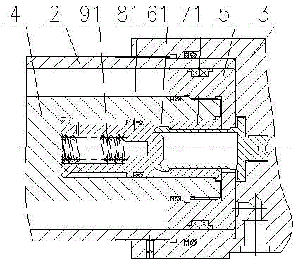
[0031] Such as figure 1 As shown, the hydraulic cylinder uses an elastic claw closed automatic locking mechanism, including cylinder barrel 2, rear cylinder cover 3, piston rod 4, piston 5, elastic outer claw 61, inner cone guide lock sleeve 71, inner anti-loosening lock Cover 81 and inner spring 91, elastic outer claw 61 are threadedly connected with rear cylinder cover 3, do not move axially. The inner spring 91 is placed in the inner anti-loosening lock sleeve 81, and is placed together in the inner hole of the piston rod 4 end. 5 Axial limit, the inner cone guide lock sleeve 71 and the inner anti-loosening lock sleeve 81 radially cooperate with the inner hole of the piston rod 4 with clearance. Piston 5, inner cone guide lock sleeve 71, inner anti-loosening lock sleeve 81, inner spring 91 move axially with piston rod 4 telescopic.
[0032] The rodless cavity is composed of piston 5, cylinder barrel 2, rear cylinder cover 3, piston rod 4, and inner locking sleeve 81, and ...
Embodiment 2
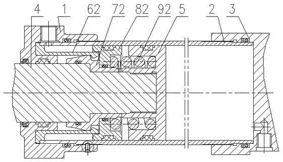
[0040] Such as figure 2 As shown, the hydraulic cylinder uses an elastic claw closed automatic locking mechanism, including cylinder barrel 2, front cylinder head 1, piston rod 4, piston 5, elastic inner claw 62, outer cone guide lock sleeve 72, outer anti-loosening lock Cover 82 and outer spring 92. The elastic inner claw 62 is placed in the front cylinder cover 1 groove, and the cylinder barrel 2 and the front cylinder cover 1 are tightened with threads. One end of the cylinder barrel 2 presses the elastic inner claw 62, and the elastic inner claw 62 is axially limited. Outer cone guide lock sleeve 72 is contained on the piston rod 4, and one axial end is limited by 4 steps of piston rod. The outer anti-loosening lock sleeve 82 is contained on the outer cone guide lock sleeve 72, and one axial end is limited by the outer cone guide lock sleeve 72. The outer spring 92 is installed in the groove of the outer anti-loosening lock sleeve 82 and the piston 5, the piston 5 and t...
Embodiment 3
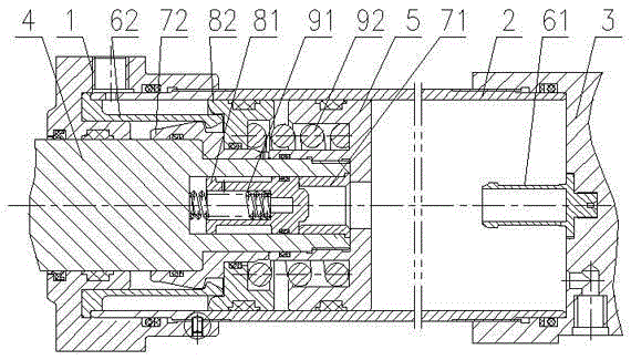
[0049] Closed automatic locking mechanism with elastic jaws for hydraulic cylinders, including front cylinder head 1, cylinder barrel 2, rear cylinder head 3, piston rod 4, piston 5, elastic outer jaws 61, elastic inner jaws 62, inner cone guide Lock sleeve 71, outer cone guide lock sleeve 72, inner anti-loosening lock sleeve 81, outer anti-loosening lock sleeve 82, inner spring 91 and outer spring 92. The elastic inner claw 62 is placed in the front cylinder cover 1 groove, and the cylinder barrel 2 is threadedly connected with the front cylinder cover 1. One end of the cylinder barrel 2 presses the elastic inner claw 62, and the elastic inner claw 62 is axially limited. Outer cone guide lock sleeve 72 is contained on the piston rod 4, and one axial end is limited by 4 steps of piston rod. The outer anti-loosening lock sleeve 82 is contained on the outer cone guide lock sleeve 72, and one axial end is limited by the outer cone guide lock sleeve 72. The outer spring 92 is ins...
PUM
 Abstract
Description
Claims
Application Information
 - R&D
- Intellectual Property
- Life Sciences
- Materials
- Tech Scout
- Unparalleled Data Quality
- Higher Quality Content
- 60% Fewer Hallucinations
Browse by: Latest US Patents, China's latest patents, Technical Efficacy Thesaurus, Application Domain, Technology Topic, Popular Technical Reports.
© 2025 PatSnap. All rights reserved.Legal|Privacy policy|Modern Slavery Act Transparency Statement|Sitemap|About US| Contact US: help@patsnap.com


