Pipe pressure anomaly diagnostic method based on combined filtering and dynamic thresholds

A combined filtering and dynamic threshold technology, applied in pipeline systems, mechanical equipment, gas/liquid distribution and storage, etc., can solve problems such as misjudgment, pipeline leakage, pressure signal distortion, etc. The method is simple, the misjudgment rate is reduced, The effect of improving sensitivity

Active Publication Date: 2014-10-08
NORTHEASTERN UNIV
View PDF5 Cites 13 Cited by
  • Summary
  • Abstract
  • Description
  • Claims
  • Application Information

AI Technical Summary

Problems solved by technology

Generally, it takes more than 10 minutes after the pipeline leaks to give diagnostic information, and if the pipeline leaks, it may lead to serious consequences
[0005] (2) It is not sensitive to small leaks and slowly changing leaks. It is generally considered that a leak with a pressure change of less than 1% within 1 minute is a small leak
Small leaks and slowly changing leaks are difficult problems in the diagnosis of pipeline leakage in active service. At present, there is no method that can completely solve this problem. We can only gradually improve the existing methods.
[0006] (3) There are many misjudgments, and the pressure signal is seriously affected by the adjustment of the working condition. When the working condition is adjusted, the pressure signal will be distorted, resulting in misjudgment

Method used


Image

  • Pipe pressure anomaly diagnostic method based on combined filtering and dynamic thresholds
  • Pipe pressure anomaly diagnostic method based on combined filtering and dynamic thresholds
  • Pipe pressure anomaly diagnostic method based on combined filtering and dynamic thresholds

Examples


Embodiment Construction

[0029] The specific embodiments of the present invention will be described in detail below in conjunction with the accompanying drawings.

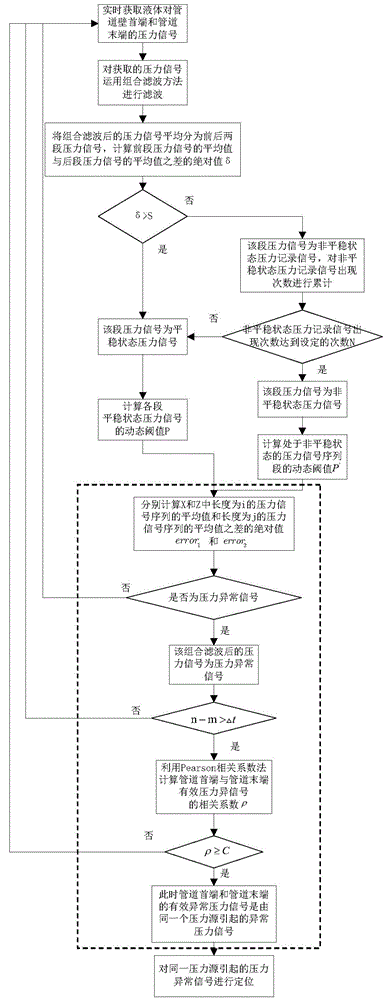
[0030] A pipeline pressure anomaly diagnosis method based on combined filtering and dynamic threshold, such as figure 1 shown, including the following steps:

[0031] Step 1: Obtain the pressure signal of the liquid on the head end of the pipeline and the pressure signal of the liquid on the end of the pipeline in real time.

[0032] The pressure signals of the liquid on the head end of the pipeline and the pressure signal of the liquid on the end of the pipeline acquired in real time contain some common high-frequency noise and some impulse pulse signals.

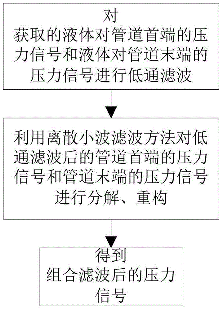
[0033] Step 2: Filter the obtained pressure signal at the head end of the liquid-to-pipeline and the pressure signal at the end of the liquid-to-pipeline using the combined filtering method. The combined filtering method is to perform low-pass filtering on the obtained pressure signal...


PUM


Abstract

The invention relates to a pipe pressure anomaly diagnostic method based on combined filtering and dynamic thresholds. The pipe pressure anomaly diagnostic method includes the steps of obtaining pressure signals of liquid to the head end and the tail end of a pipe in real time, carrying out decomposition reconstruction through low-pass filtering and discrete wavelet filtering, obtaining pressure signals generated after combined filtering, carrying out segment treatment on the pressure signals, calculating the dynamic thresholds of the segmented pressure signals obtained after combined filtering, judging whether the pressure signals of the pipe are abnormal or not in real time through the dynamic thresholds, judging whether the pressure anomaly signals at the head end and the tail end of the pipe are pressure anomaly signals caused by a same source or not with the Pearson related coefficient method, carrying out continuous wavelet transformation on the pressure anomaly signals with the same source to obtain moments corresponding to the maximum value points of wavelet coefficients, and carrying out anomaly point positioning through the difference of the moments corresponding to the maximum value points. By means of the pipe pressure anomaly diagnostic method, the pipe anomaly diagnostic sensitivity is improved, the misjudgment rate is reduced, and pressure anomaly points are accurately detected and positioned in the shortest time.

Description

technical field [0001] The invention belongs to the field of fault detection for fluid storage and transportation monitoring, in particular to a pipeline pressure abnormality diagnosis method based on combined filtering and dynamic threshold. Background technique [0002] Among the real-time detection methods of pipeline leakage, the pipeline leakage diagnosis method based on pressure wave has been widely used due to its simple principle and structure. According to incomplete statistics, leak detection systems based on pressure waves have been installed on at least 20,000 kilometers of long-distance pipelines in my country. Although the new leak detection methods based on optical fiber, acoustic wave or resistance network have been relatively mature, their application is not limited because of the characteristics of real-time leak diagnosis system based on pressure signal. [0003] The real-time diagnosis system based on pressure signal leakage is a diagnostic technology wi...

Claims


Application Information

Patent Timeline
Patent Type & Authority Applications(China)
IPC IPC(8): F17D5/02
Inventor 刘金海吴振宁马大中张化光冯健汪刚于洋卢森骧李芳明
Owner NORTHEASTERN UNIV
Why Eureka
Try Eureka