Straight down type backlight source module

A backlight, direct-type technology, applied in the field of direct-type backlight module, can solve problems such as brightness drop, influence on light mixing, thermal quenching of phosphor powder, etc., to reduce the light mixing distance, save the number of light sources, light Evenly spread effect

Active Publication Date: 2014-10-08
BOE TECH GRP CO LTD +1
View PDF6 Cites 2 Cited by
  • Summary
  • Abstract
  • Description
  • Claims
  • Application Information

AI Technical Summary

Problems solved by technology

However, the secondary optical lens itself will occupy a certain thickness, which also limits the ultra-thinning of the backlight module to a certain extent.
In addition, there is a certain matching problem between the existing secondary optical lens and the LED, that is, if the matching between the two is not good, it will direc

Method used


Image

  • Straight down type backlight source module
  • Straight down type backlight source module
  • Straight down type backlight source module

Examples


Embodiment 1

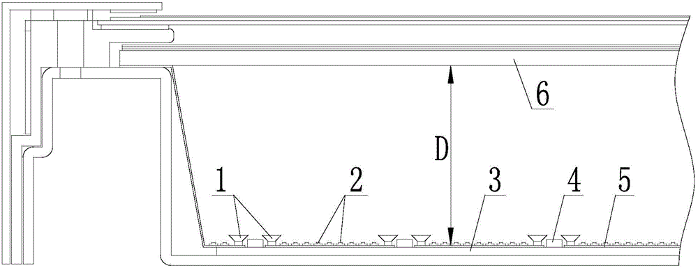
[0033] The direct type backlight module in this embodiment, such as Figure 2-Figure 6 As shown, it includes a light source 4, a back plate 3, a reflection sheet 5, a diffusion plate 6, a light scattering device 1 and diffusion particles 2, the reflection sheet 5 is located above the back plate 3, the diffusion plate 6 is located above the reflection sheet 5, and the light source 4 is located Between the back plate 3 and the diffusion plate 6 ; the light scattering device 1 is arranged around the light source 4 and between the back plate 3 and the diffusion plate 6 ; the diffusion particles 2 are all arranged on the reflection sheet 5 .

[0034] In this embodiment, the astigmatism device 1 is a trumpet-shaped structure, including a large end and a small end, and the small end is fixedly connected to the back plate 3, as image 3 and Figure 4 shown; and the astigmatism device 1 is evenly arranged on the backplane 3, as Figure 5 and Figure 6 shown.

[0035] In order to fu...

Embodiment 2

[0040] The difference between the backlight module in this embodiment and the first embodiment is that the structure of the astigmatism device is different. The astigmatism device 1 in this embodiment is a mushroom-shaped structure, such as Figure 7 As shown, including a spherical surface and a flat surface, the spherical surface is arranged upwards, which can also achieve the purpose of spreading the light more uniformly in the first embodiment, that is, reducing the light mixing distance and realizing the ultra-thinning of the backlight module. Furthermore, the number of LED light sources can also be reduced.

[0041] It should be noted that, in the above two embodiments, the structure of the light astigmatism device 1 is not limited to the trumpet-shaped structure in the first embodiment and the mushroom-shaped structure in the second embodiment, but can also be other existing known shapes and structures.

[0042] The arrangement of the astigmatism device 1 is not limited ...


PUM


Abstract

The invention provides a straight down type backlight source module. The straight down type backlight source module comprises light sources, a backboard, a reflection sheet and a diffusion board. The reflection sheet is located above the backboard, the diffusion board is located above the reflection sheet, the light sources are located between the backboard and the diffusion board, and a plurality of light diverging devices are arranged around the light sources and located between the backboard and the diffusion board. According to the straight down type backlight source module, light irradiated on the diffusion device can be refracted, light between the light sources and the diffusion board can be effectively diffused more evenly, the light mixing distance between the light sources and the diffusion board is reduced, the ultra-thin design of the straight down type backlight source module is achieved, and the number of the light sources is reduced.

Description

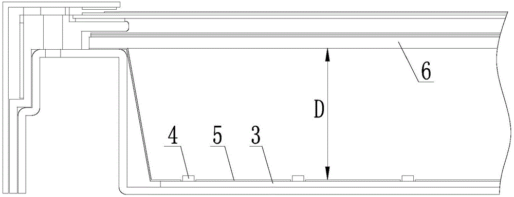
technical field [0001] The invention relates to a direct-type backlight source module, which belongs to the technical field of display. Background technique [0002] LED-backlit LCD TV has the outstanding advantages of low energy consumption, long life, wide color gamut and environmental protection, and has become the mainstream of LCD TV. Among them, large-size LED backlight has become a new trend in the development of the LCD TV industry. The large-size backlight mainly adopts the direct type, because the LED light source of the direct type LED backlight module has a high distribution density on the PCB, and the light between the LED light sources is easy to cross and mix. Generally speaking, to improve brightness uniformity, the distance from the diffusion plate to the LED light source must be increased. Increasing this distance also increases the thickness of the module, which is not conducive to the development of ultra-thin, such as figure 1 shown. [0003] How to r...

Claims


Application Information

Patent Timeline
IPC IPC(8): F21S8/00F21V13/04F21V17/00G02F1/13357F21Y101/02
Inventor 张伟马青尹大根廖燕平
Owner BOE TECH GRP CO LTD
Why Eureka
Try Eureka