Novel micro-channel heat exchanger

A micro-channel heat exchanger and a new type of technology, applied in the field of heat exchange, can solve the problems of insufficient heat exchange and low heat exchange efficiency, and achieve the effects of improving heat exchange efficiency, facilitating heat exchange, and being easy to form.

Active Publication Date: 2014-10-08
HANGZHOU SHENSHI ENERGY CONSERVATION TECH
View PDF6 Cites 6 Cited by
  • Summary
  • Abstract
  • Description
  • Claims
  • Application Information

AI Technical Summary

Problems solved by technology

[0005] For this reason, the technical problem to be solved by the present invention is that in the microchannel parallel flow heat exchanger in the prior art, the fins and the headers are arranged in layers, the heat exchange is

Method used


Image

  • Novel micro-channel heat exchanger
  • Novel micro-channel heat exchanger
  • Novel micro-channel heat exchanger

Examples


Embodiment 1

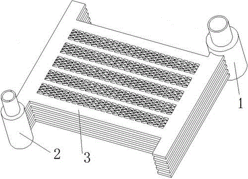
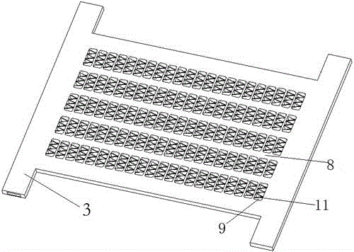
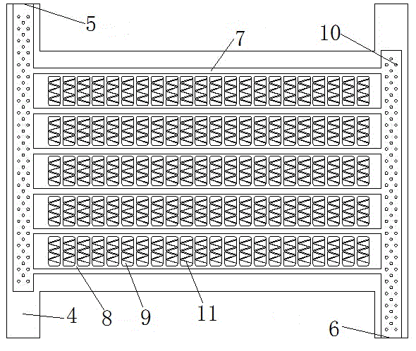
[0036] Such as Figure 1-Figure 5 As shown, a microchannel heat exchanger described in this embodiment includes a first header 1, a second header 2, and the first header 1 and the second header A heat exchange assembly connected by pipes 2, the heat exchange assembly includes several heat exchange units 3, such as figure 2 and image 3 As shown, the heat exchanging unit 3 includes two heat exchanging fins 4 that are butted together as a whole, and a concave groove is formed on the butt joint surface of the heat exchanging fins 4 , and after the butt joint faces of the two heat exchanging fins 4 are abutted, , the butted concave groove forms a fluid channel, and the flow channel includes an inlet channel 5, an outlet channel 6, and several intermediate channels 7 connecting the inlet channel 5 and the outlet channel 6, in this embodiment Among them, the middle passage 7 is set to 6; the heat exchange fin 4 is also provided with a number of molded between two adjacent middle ...

Embodiment 2

[0045] Such as Figure 6 As shown, as a transformable embodiment of embodiment 1, the differences between this embodiment and embodiment 1 are:

[0046] The joints between each end point of the "V"-shaped sheet and the adjacent fins 7 are formed in an arc shape.

Embodiment 3

[0048] Such as Figure 7 As shown, as a transformable embodiment of embodiment 1, the differences between this embodiment and embodiment 1 are:

[0049] The auxiliary fins 11 include a number of "V"-shaped fins arranged in rows or columns in the ventilation groove 9 and arranged at intervals. The auxiliary fins 11 are simple in structure and easy to form, and the sheet structure is convenient for sufficient heat exchange between the fluid and the heat exchange, and the ends of the two arms of the "V"-shaped sheet are connected to the adjacent fins 8 , so that the heat of the fluid in the middle channel 7 can be quickly transferred to the auxiliary fins 11 through the fins 8 .

[0050] Wherein, the auxiliary fins 11 also have some preferred dimensions, for example, the spacing S1 between two adjacent auxiliary fins 11 is not greater than 2 mm, and the thickness S2 of the auxiliary fins 11 is not greater than 0.5 mm. The included angle α of the auxiliary fins is not greater th...


PUM

PropertyMeasurementUnit
Hydraulic diameteraaaaaaaaaa
Inner wall diameteraaaaaaaaaa
Thicknessaaaaaaaaaa

Abstract

The invention discloses a novel micro-channel heat exchanger which comprises a first header pipe, a second header pipe and a heat exchange assembly communicated with the first header pipe and the second header pipe. The heat exchange assembly comprises a plurality of heat exchange units. Each heat exchange unit comprises two heat exchange pieces which are in butt joint to form a whole, wherein concave grooves are formed in butt joint faces of the two heat exchange pieces, and after the butt joint faces of the two heat exchange pieces are in butt joint, the butt joint concave grooves form a fluid channel. Each fluid channel comprises an inlet channel, an outlet channel and multiple middle channels enabling the inlet channel to be communicated with the outlet channel. Each heat exchange piece is further provided with multiple fins formed between two adjacent middle channels and formed by multiple ventilating slots distributed in columns in the length direction of the middle channels, and auxiliary fins are further arranged in the ventilating slots. The fins and circulating channels are arranged on the same level, gas needing heat exchange is fed in perpendicular to the heat exchange pieces, heat exchange is carried out on gas and fluid in the middle channels through the ventilating slots in a multidirectional mode, and therefore sufficient heat exchange is achieved. The heat exchange efficiency of the heat exchanger is high.

Description

technical field [0001] The invention relates to a device in the field of heat exchange, in particular to a novel microchannel heat exchanger. Background technique [0002] Microchannel heat exchanger is a three-dimensional structural unit that can be used for heat exchange between media manufactured by special processing methods. At present, regarding the exact definition of microchannel heat exchangers, a more general and intuitive classification is proposed by Mehendale.s.s, which is divided according to the hydraulic diameter of the flow channel. Generally speaking, the hydraulic diameter of the flow channel is in the range of 0.1~1mm The heat exchanger inside is called a microchannel heat exchanger. The microchannel heat exchanger has the characteristics of compact structure, high heat exchange efficiency, light weight, safe and reliable operation, etc. Because microchannel heat exchangers have many incomparable advantages over conventional size heat exchangers, the re...

Claims


Application Information

Patent Timeline
IPC IPC(8): F28D1/03F28F3/02F28F13/12F28F9/26
Inventor 吴小辉沈卫立
Owner HANGZHOU SHENSHI ENERGY CONSERVATION TECH
Why Eureka
Try Eureka