
Metal film optical detection device and detection method

An optical detection and metal film technology, which is applied in the direction of using optical devices, measuring devices, and optical testing for flaws/defects, can solve problems such as metal film surface damage and probe metal film contact, so as to avoid contact, avoid damage, and improve The effect of production efficiency

Active Publication Date: 2014-10-08
TCL CHINA STAR OPTOELECTRONICS TECH CO LTD
View PDF7 Cites 14 Cited by
  • Summary
  • Abstract
  • Description
  • Claims
  • Application Information

AI Technical Summary

Problems solved by technology

[0004] However, this level difference measuring machine has the following disadvantages: the contact between the probe and the metal film
This kind of contact measurement will cause certain damage to the surface of the metal film

Method used


Image

  • Metal film optical detection device and detection method
  • Metal film optical detection device and detection method
  • Metal film optical detection device and detection method

Examples


Embodiment Construction

[0026] The present invention will be further described below in conjunction with accompanying drawing.

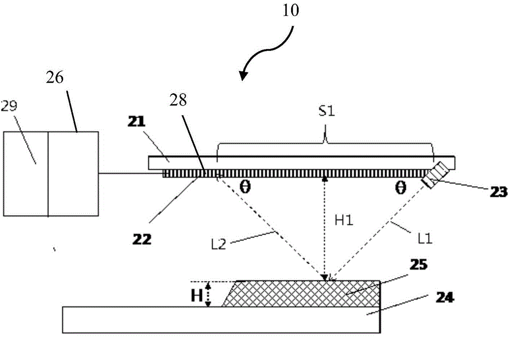
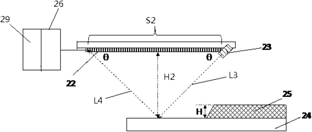
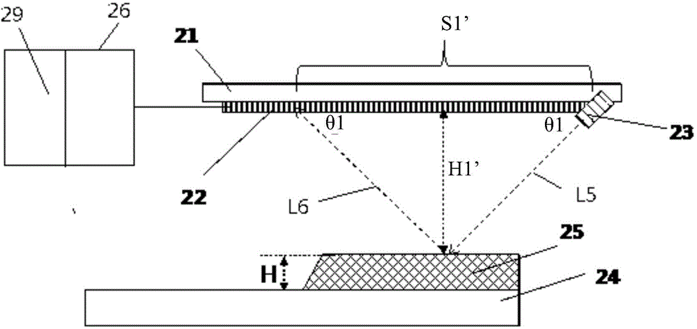
[0027] figure 1 with figure 2 Schematically shows the principle of using the metal film optical detection device 10 of the present invention (hereinafter referred to as the device 10 ) to measure the thickness of the metal film. Firstly, the components included in the device 10 will be described: a carrier 21 , a photosensitive sensor 22 and a light source 23 arranged on the carrier 21 , and an analysis unit 26 connected to the photosensitive sensor 22 . Such as figure 1 or figure 2 As shown, when the device 10 is used, the light source 23 obliquely faces the metal film 25 and the substrate 24 , so that the incident light beam L1 strikes the metal film 25 and the substrate 24 at an angle θ with the carrier 21 . The photosensitive sensor 22 also faces the metal film 25 and the substrate 24 with measurement to receive the reflected light beam L2 from the metal film 25 a...


PUM

PropertyMeasurementUnit
areaaaaaaaaaaa

Abstract

The invention relates to a metal film optical detection device and detection method. The device comprises a load receptor and an analysis unit, wherein a light source slantly facing a metal film and a substrate is arranged at the first position of the load receptor, a photosensitive sensor for receiving a reflected light beam from the metal film or the substrate is arranged at the second position of the load receptor, and the analysis unit is used for processing light signals from the photosensitive sensor. The analysis unit can obtain the thickness of the metal film according to the included angle between an incident light beam and the load receptor, the first length between a first reflection light spot corresponding to the metal film and the light source, and the second length between a second reflection light spot corresponding to the substrate and the light source. The metal film optical detection device can measure the thickness of the metal film in a mode of not being in contact with the metal film, and the measuring precision is high.

Description

technical field [0001] The invention relates to the field of liquid crystal display manufacture, in particular to a metal film optical measuring device. The invention also relates to a detection method using the metal film optical measurement device. Background technique [0002] Thin Film Field Effect Transistor Liquid Crystal Displays (ie, TFT-LCDs) are currently the most popular type of displays, which are widely used in electronic devices. TFT-LCD is a precision display that requires precise control of its various production steps. [0003] In the production process of the array substrate of the TFT-LCD, it is necessary to precisely control the thickness of the metal film formed on the array substrate. At present, the step difference measuring machine is usually used to measure the thickness of the metal film. The measuring principle of the step difference measuring machine is: touch a probe to the surface of the sample. Move the probe in the horizontal direction, an...

Claims


Application Information

Patent Timeline
Patent Type & Authority Applications(China)
IPC IPC(8): G01B11/06G01N21/84
CPCG01B11/06G01N21/88
Inventor 柴立张正义陈一翔
Owner TCL CHINA STAR OPTOELECTRONICS TECH CO LTD
Learn More