Spring fatigue test device

A fatigue test and detection technology, applied in the field of mechanical equipment, can solve the problems of long test time, inability to timely feedback automatic operation, and low frequency.

Active Publication Date: 2014-10-08
CHANGZHOU INST OF MECHATRONIC TECH
View PDF6 Cites 10 Cited by
  • Summary
  • Abstract
  • Description
  • Claims
  • Application Information

AI Technical Summary

Problems solved by technology

Existing spring fatigue test equipment has a wide variety of detection methods, such as linear reciprocating compression springs, the frequency is relatively low, and the test time is long; in addition, the invention of Chinese patent application No. 200920299671.7 discloses a method for spring fatigue test The device includes a housing, a motor, a rotating shaft connected to the motor, and a rotating wheel connected to the rotating shaft is set in the cavity of the housing, the inner cavity of the housing is set in an elliptical structure, and the rotating wheel is set as a plurality of impellers The multiple impellers on the rotating wheel are equipped with spring seat mounting holes, and the springs used for detection are assembled on the spring mounting seats, and are jointly assembled on the spring mounting holes set on the impellers. The device has a simple structure and realizes rapid detection. The service life of the spring, but its shortcomings are also very obvious. The device cannot timely feedback the test status of the spring and realize the automatic operation of the entire test process. In addition, when the spring is installed and tested, the assembly process is difficult, and the spring cannot be tested The temperature of the area is adjusted, which has certain limitations for the durability of the simulated spring.

Method used


Image

  • Spring fatigue test device
  • Spring fatigue test device

Examples


Embodiment Construction

[0017] In order to make the content of the present invention more clearly understood, the present invention will be further described in detail below based on specific embodiments and in conjunction with the accompanying drawings.

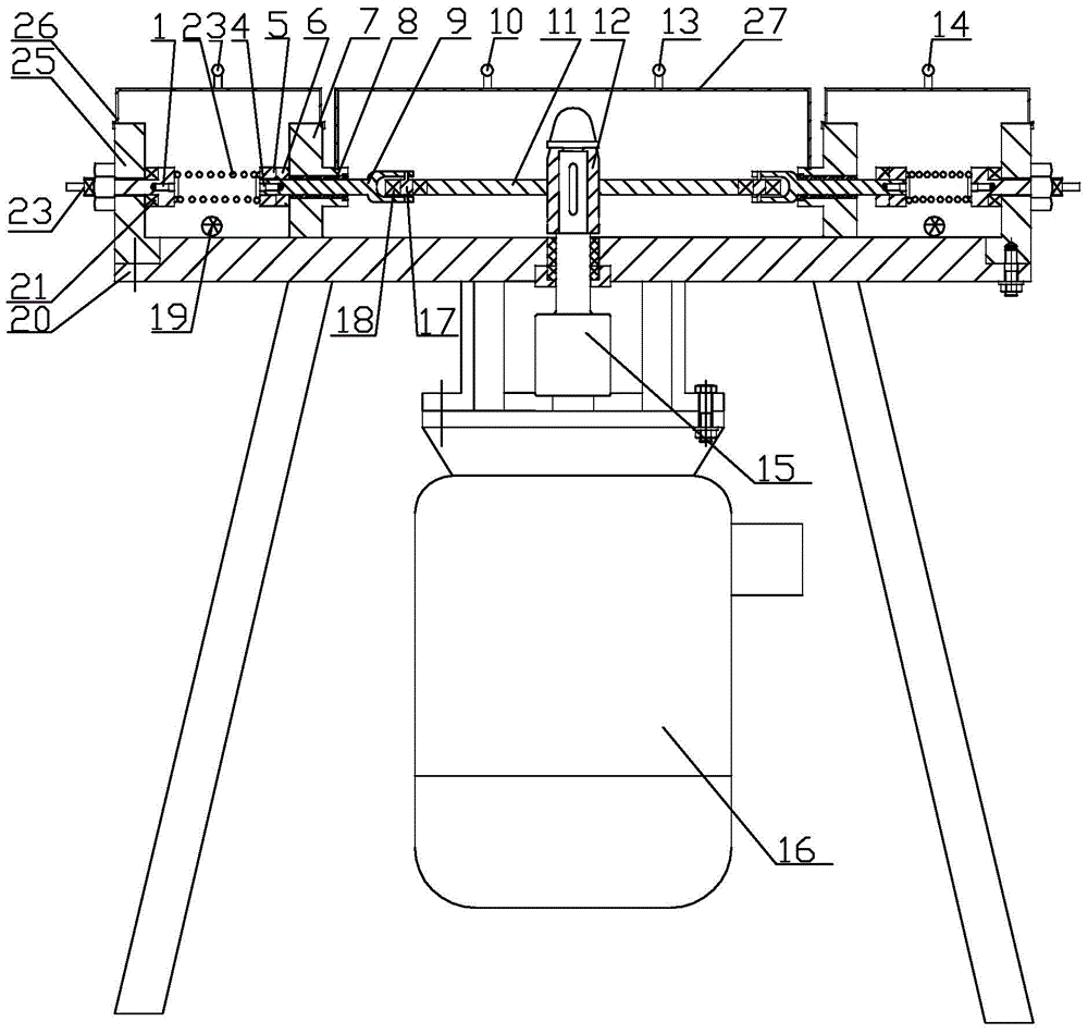
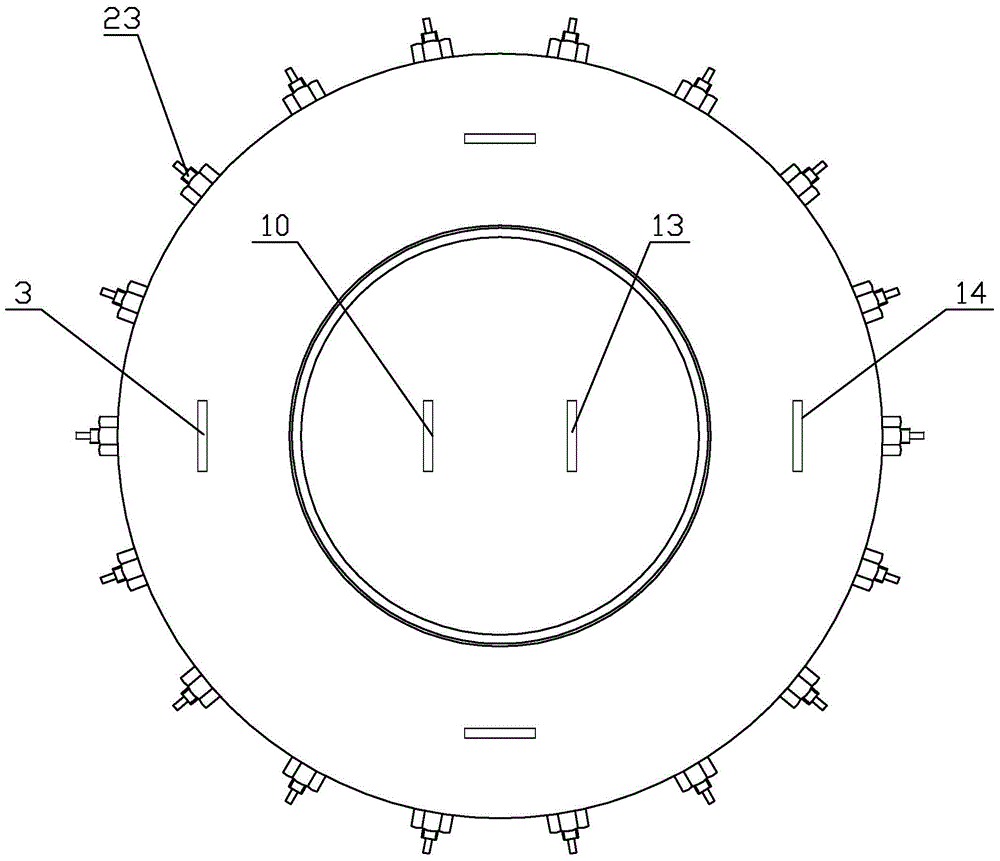
[0018] Such as figure 1 , 2 Shown, a kind of spring fatigue testing device, it comprises pressure sensor 21, control panel, support body, cam 11 and the transmission mechanism that drives cam 11 to rotate and at least one spring holding mechanism, and spring holding mechanism includes follower piston assembly and The base assembly and the follower piston assembly are slidingly fitted on the support body. One end of the follower piston assembly is in active contact with the cam 11 so that when the cam 11 rotates, the follower piston assembly is pushed to move relative to the support body. The detected spring 2 is installed on the follower Between the other end of the piston assembly and the base assembly, the pressure sensor 21 is installed on the ...


PUM


Abstract

The invention discloses a spring fatigue test device. The spring fatigue test device comprises a pressure sensor, a control panel, a supporting body, a cam, a transmission mechanism and at least one spring clamping mechanism, wherein the transmission mechanism drives the cam to rotate. The spring clamping mechanism comprises a slave piston assembly and a base assembly. The slave piston assembly is in sliding fit with the supporting body. One end of the slave piston assembly makes movable contact with the cam, so that when the cam rotates, the slave piston assembly is pushed to move relative to the supporting body. A tested spring is arranged between the other end of the slave piston assembly and the base assembly, the pressure sensor is arranged on the base assembly so as to sense pressure of the tested spring, and the signal output end of the pressure sensor is connected with the signal input end of the control panel through a pressure signal output terminal. The signal output end of the control panel is in control connection with the transmission mechanism, so that starting and stopping of the transmission mechanism are controlled according to pressure signals of the pressure sensor. The spring fatigue test device can monitor and feed back the status of the tested spring in real time, automation of a testing process is achieved completely, the tested spring is convenient to dismount and mount, and labor intensity is reduced.

Description

technical field [0001] The invention relates to a spring fatigue testing device, which belongs to the technical field of mechanical equipment. Background technique [0002] At present, the spring fatigue testing machine is a kind of testing equipment used to evaluate the service life of springs, especially the engine valve springs of automobiles and other springs with high operating frequency and relatively long operating distance. The latest national standard requires 23 million operating times. Second-rate. Existing spring fatigue test equipment has a wide variety of detection methods, such as linear reciprocating compression springs, the frequency is relatively low, and the test time is long; in addition, the invention of Chinese patent application No. 200920299671.7 discloses a method for spring fatigue test The device includes a housing, a motor, a rotating shaft connected to the motor, and a rotating wheel connected to the rotating shaft is set in the cavity of the ho...

Claims


Application Information

Patent Timeline
Patent Type & Authority Applications(China)
IPC IPC(8): G01M13/00
Inventor 王峰田宏霞岳兴莲
Owner CHANGZHOU INST OF MECHATRONIC TECH
Why Eureka
Try Eureka