Method of analyzing sample and charged particle beam device for analyzing sample

A technology of charged particle beams, charged particles, applied in the direction of analyzing materials, measuring devices, material analysis using radiation diffraction, etc.

Active Publication Date: 2014-10-08
CARL ZEISS MICROSCOPY GMBH
View PDF7 Cites 7 Cited by
  • Summary
  • Abstract
  • Description
  • Claims
  • Application Information

AI Technical Summary

Problems solved by technology

This makes it almost impossible to clearly distinguis...

Method used


Image

  • Method of analyzing sample and charged particle beam device for analyzing sample
  • Method of analyzing sample and charged particle beam device for analyzing sample
  • Method of analyzing sample and charged particle beam device for analyzing sample

Examples


Embodiment Construction

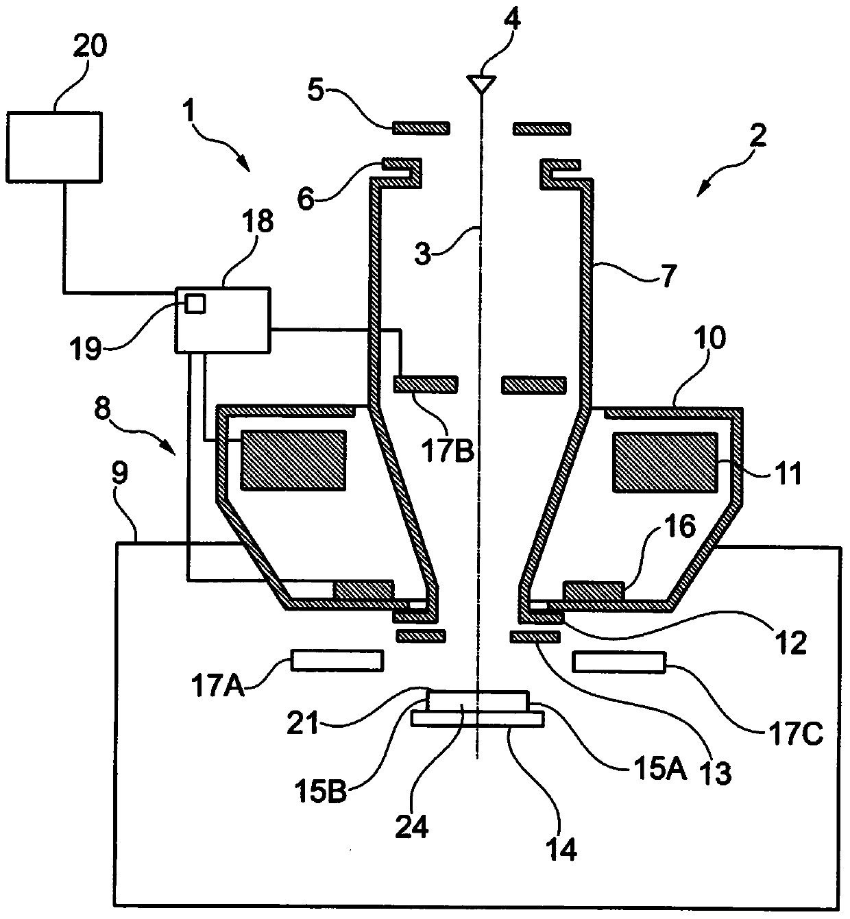
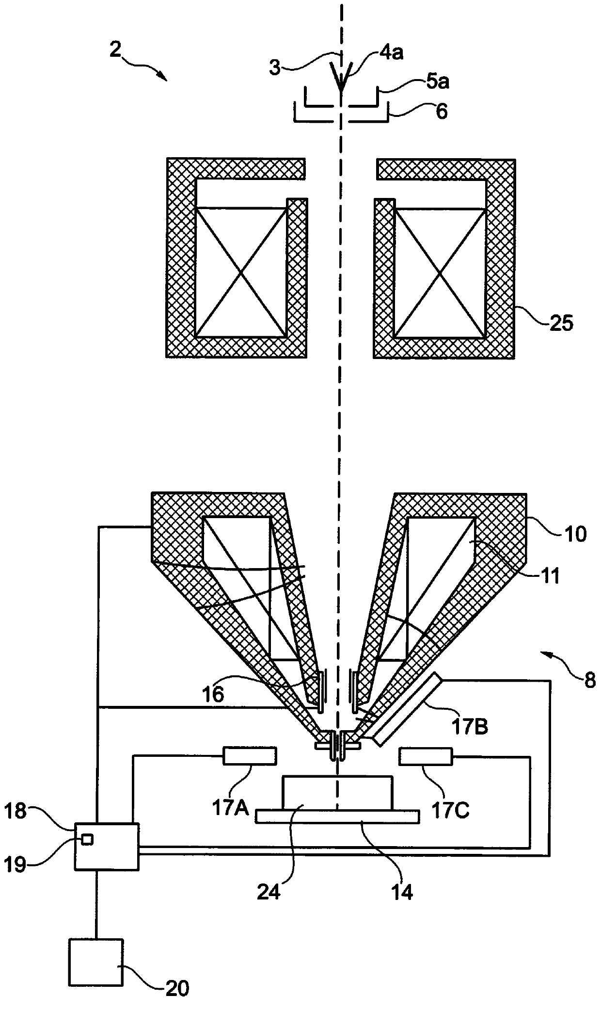
[0034] figure 1 A schematic diagram of a charged particle beam device 1 in the form of a SEM is shown, comprising a charged particle beam column 2 embodied as an electron beam column. However, it should be expressly noted that the invention is not limited to SEM. Rather, the invention can be used in any charged particle beam device, especially as an ion beam device.

[0035] The charged particle beam column 2 has an optical axis 3, a beam generator 4 in the form of an electron source (cathode), a first electrode 5 in the form of an extraction electrode and a second electrode 6 in the form of an anode which at the same time forms the beam guide One end of tube 7. By way of example, the beam generator 4 is a thermal field emitter. Electrons from the beam generator 4 are accelerated to the anode potential by the potential difference between the beam generator 4 and the second electrode 6 . Accordingly, a beam of charged particles in the form of an electron beam is provided. ...


PUM


Abstract

The invention refers to a method and a charged particle beam device (1) for analyzing an object (24) using a charged particle beam interacting with the object (24). The object (24) comprises a sample (15A) embedded in a resin (15B). Interaction radiation in the form of cathodoluminescence light is detected for identifying areas in which the resin (15B) is arranged and in which the sample (15A) is arranged. Interaction particles are detected to identify particles within the resin (15B) and the sample (15A) for further analysis by using EDX analysis.

Description

technical field [0001] The present application relates to a method of analyzing a sample using a charged particle beam device and a charged particle beam device for analyzing a sample. Background technique [0002] It is often important to know the composition of materials used in different technical fields. One of these materials is coal. Coal is, for example, an important source of electricity production worldwide. In particular, coal is burned to provide energy to drive steam turbines that generate electricity. Coal consists primarily of carbon from plant material and naturally contains minerals. The mineral content of coal can be as high as 30% of the coal's composition. Minerals present in coal are eg silicates, clays, carbonates, oxides and sulfides. The exact amount of minerals in the coal can vary. [0003] Minerals in coal are generally non-combustible and cause negative effects. In particular, they reduce the calorific value of the coal and end up as ash par...

Claims


Application Information

Patent Timeline
IPC IPC(8): G01N23/20G01N23/22
CPCH01J37/26G01N23/2254H01J2237/2804H01J2237/2806H01J2237/2808H01J2237/2809
Inventor E.希尔S.比恩
Owner CARL ZEISS MICROSCOPY GMBH
Why Eureka
Try Eureka