Arrayed Waveguide Grating Wavelength Division Multiplexer

A technology of arrayed waveguide grating and wavelength division multiplexer, which is applied in the directions of light guide, optics, instruments, etc., can solve the problems such as easy deformation of temperature compensation rod or temperature compensation sheet, poor structural stability, complex mechanical structure, etc.

Active Publication Date: 2017-03-29
SHENZHEN GIGALIGHT TECH
View PDF6 Cites 0 Cited by
  • Summary
  • Abstract
  • Description
  • Claims
  • Application Information

AI Technical Summary

Problems solved by technology

However, this solution also has the following defects: 1. The arrayed waveguide grating wavelength division multiplexer chip is cut into two parts, and the optical coupling needs to be re-coupled. Since the optical waveguide is only a few microns thick, a very precise adjustment device is required for the light, and the adjustment The adjustment space is limited, and the coupling adjustment is very difficult
2. Since the temperature compensation rod or the temperature compensation sheet is connected to a part of the active substrate where the arrayed waveguide grating chip is located, most of them are in a suspended state, and all the force of the suspended part is borne by the temperature compensation rod or temperature compensation sheet, so that the temperature compensation rod or temperature compensation sheet is easy to Deformation occurs, and it is easily affected by external vibration and impact, which changes the position of the light and poor structural stability
3. The mechanical structure is complex, and it is easy to fail after high temperature baking and high and low temperature cycles

Method used


Image

  • Arrayed Waveguide Grating Wavelength Division Multiplexer
  • Arrayed Waveguide Grating Wavelength Division Multiplexer
  • Arrayed Waveguide Grating Wavelength Division Multiplexer

Examples


Embodiment Construction

[0023] The specific implementation manners of the present invention will be described in detail below in conjunction with the accompanying drawings.

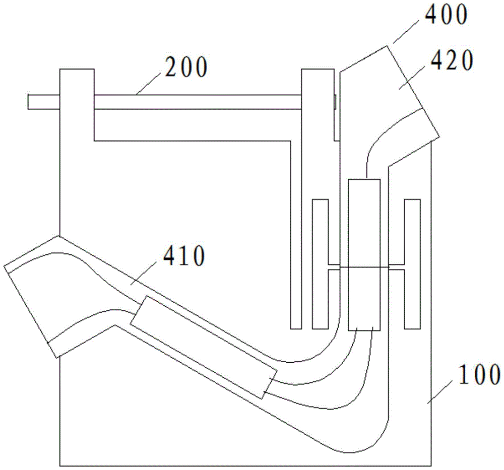
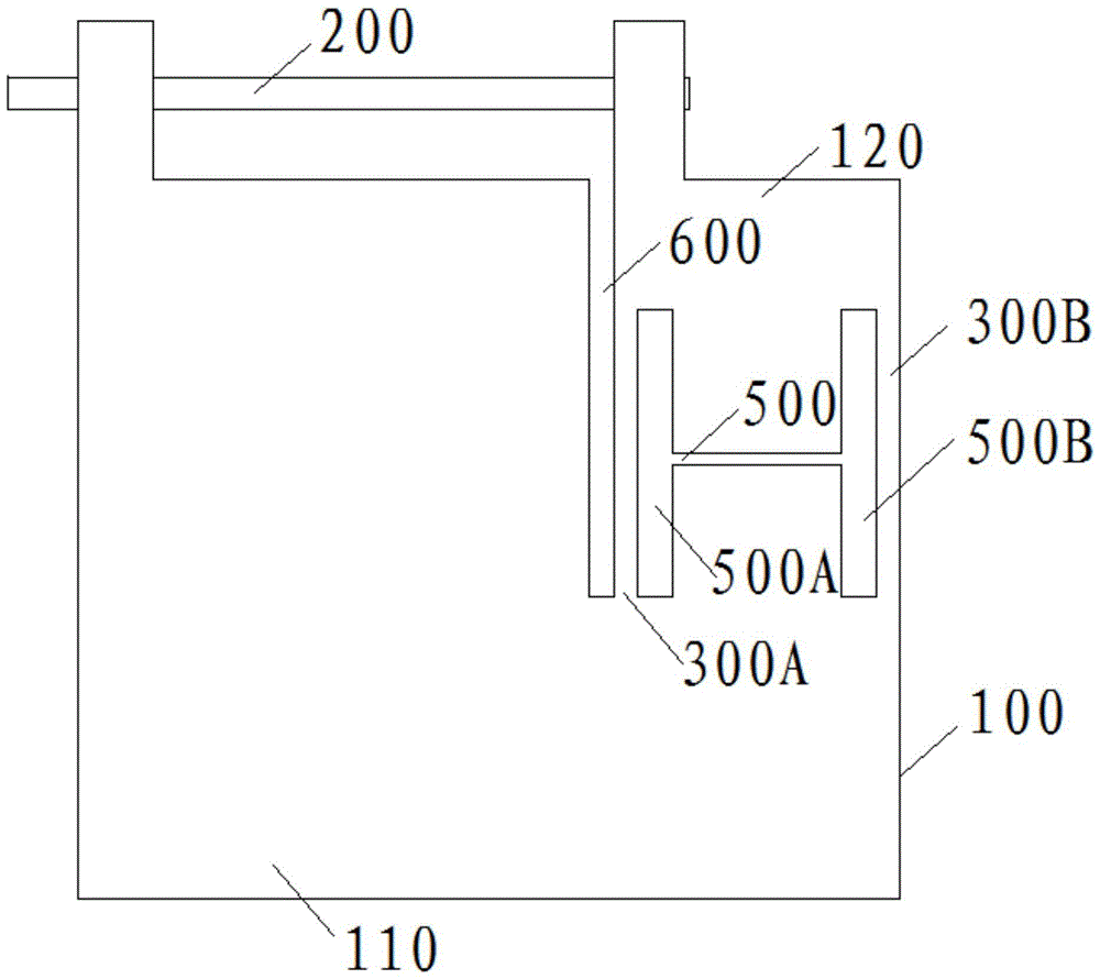
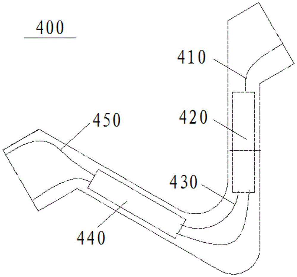
[0024] An arrayed waveguide grating wavelength division multiplexer includes a base plate, a telescopic part, a support part and an arrayed waveguide grating chip, and the telescopic part expands and contracts as the temperature changes.

[0025] The arrayed waveguide grating chip is pasted on the substrate, the substrate and the arrayed waveguide grating chip are cut separately, the substrate is cut into a first substrate and a second substrate, and a cutting slit is formed between the first substrate and the second substrate, and the arrayed waveguide grating chip is cut Cutting and separating into a first part of chips and a second part of chips, the telescopic part connects the first substrate and the second substrate, the angle between the telescopic part and the cutting slit is not equal to 90°, and the supporting part conn...


PUM


Abstract

The invention discloses an array waveguide grating wavelength division multiplexer. The array waveguide grating wavelength division multiplexer comprises a supporting part for making two separated chip parts of an array waveguide grating chip move more stably in the relative movement process, a retractable part stretching and retracting along with changes of temperature makes the supporting part generate deformation in the direction of a cutting seam, and therefore a first substrate and a second substrate can have dislocation movement in the direction of the cutting seam, and the first chip part and the second chip part have dislocation movement in the direction of the cutting seam. Due to the supporting part, the array waveguide grating chip can be attached to the substrates and then cut, and beam-focusing coupling does not need to be performed again. The supporting part can support the movable substrates where the array waveguide grating chip is located, structural stability is enhanced, and the two separated chip parts of the array waveguide grating chip are made to move more stably in the relative movement process.

Description

technical field [0001] The invention relates to the field of optical equipment, in particular to an arrayed waveguide grating wavelength division multiplexer. Background technique [0002] Arrayed Waveguide Grating wavelength division multiplexer (AWG, Arrayed Waveguide Grating) is a device made of planar optical path technology. device) and the output waveguide array consists of five parts. The input signal is distributed to each arrayed waveguide by the input slab waveguide, and the length of the arrayed waveguide is increased by ΔL in turn, and the optical path difference is generated for the passing optical signal. Its function is equivalent to a grating, and diffraction occurs at the output position of the arrayed waveguide. Different wavelengths are diffracted to different angles and focused into different output waveguides through the output slab waveguide. [0003] However, since the ordinary AWG is made of silicon-based silicon dioxide technology, the refractive i...

Claims


Application Information

Patent Timeline
Patent Type & Authority Patents(China)
IPC IPC(8): G02B6/293G02B6/122
Inventor 张钟铁李振东
Owner SHENZHEN GIGALIGHT TECH
Why Eureka
Try Eureka