A terahertz detector based on an optical antenna

A terahertz detector and optical antenna technology, applied in the field of terahertz signal detection, can solve problems such as unfavorable detector array integration, limited detector voltage response, limited radio antenna gain, etc., and achieves favorable integration and reduces design difficulty. , the effect of reducing the detector area

Active Publication Date: 2016-09-28
NANJING UNIV
View PDF5 Cites 0 Cited by
  • Summary
  • Abstract
  • Description
  • Claims
  • Application Information

AI Technical Summary

Problems solved by technology

[0004] However, the above-mentioned detectors still use the traditional radio wave antenna made of metal, and the size of the antenna is at least 1 / 2 wavelength, which is relatively large, which is not conducive to the integration of the detector array.
At the same time, the gain of the radio wave antenna is limited, and the voltage response of the detector made of the radio wave antenna is limited

Method used


Image

  • A terahertz detector based on an optical antenna
  • A terahertz detector based on an optical antenna
  • A terahertz detector based on an optical antenna

Examples


Embodiment Construction

[0020] In order to make the content of the present invention clearer, the implementation manner of the present invention will be further described in detail below in conjunction with the accompanying drawings.

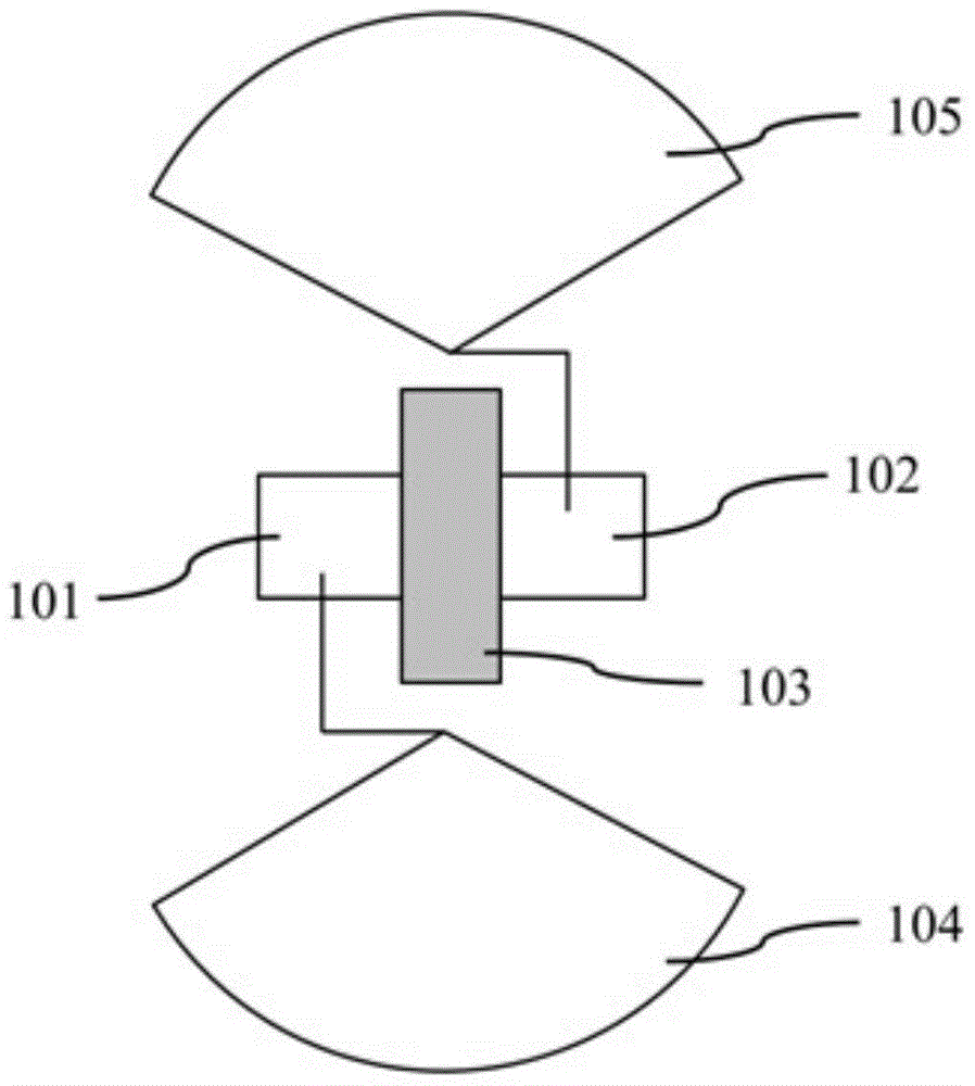
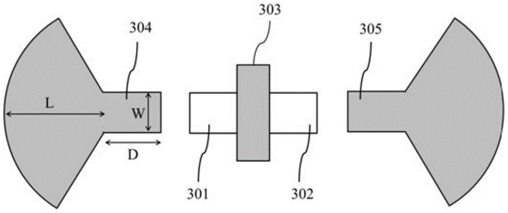
[0021] image 3 Shown is a schematic plan view of the structure of the terahertz detector based on the optical antenna of the present invention. Polysilicon is used as the antenna material, and the antennas 304 and 305 are respectively placed at the two ends of the source terminal 301 and the drain terminal 302 of the transistor. The two ends 304 and 305 of the antenna are formed by a polysilicon layer, and the two ends of the antenna are respectively placed at the two ends of the source 301 and the drain 302 of the transistor, and the transistor gate 303 is located in the middle of the antenna gap, and the transistor gate 303 is also a polysilicon layer, and the gate length is The size is 50-300nm. The transistor gate 303 is subjected to a silicon metallization (sil...


PUM


Abstract

An optical antenna-based terahertz detector comprising optical antennas (104 and 105) made of a polysilicon material layer and a transistor or a field-effect transistor. The optical antennas (104 and 105) respectively are arranged at either end of a source electrode (101) and a drain electrode (102) of the transistor. The edges of the antennas (104 and 105) are distanced from the edges of a transistor gate electrode (103) at a pitch of 100-500 nm. The optical antennas are separated from the source terminal (101), the drain terminal (102), and the gate terminal (103) of the transistor via an oxide filler in a standard process. The optical antennas (104 and 105) and the transistor gate electrode (103) employ a same layer of polysilicon material, are doped via other processes for independent implementation, and have a thickness of 100-300 nm. An antenna structure of a dipole antenna or of a bowtie antenna is employed for the optical antennas (104 and 105), where the doping concentration of the polysilicon material is 1017-1020. A work solution of the terahertz detector of the optical antennas (104 and 105) is such that a direct-current offset voltage is applied to the transistor gate electrode (103), the source electrode (101) is grounded, the drain electrode (102) is suspended in mid air, and a signal voltage is outputted from the drain electrode (102).

Description

technical field [0001] The invention relates to the field of terahertz signal detection, and further relates to a detector structure using an optical antenna as a signal receiving component, which can achieve greater response. Background technique [0002] Terahertz is an electromagnetic wave with a frequency between infrared and microwave, which has many unique properties. Due to the high frequency of terahertz, its spatial resolution and temporal resolution are very high. At the same time, many non-metallic polar materials have little absorption of terahertz rays, so they can detect the internal information of the material. In addition, the terahertz electromagnetic energy is small and will not damage the material, and the resonance frequency of the vibration and rotation frequency of biomolecules is in the Terahertz band, so terahertz also has good application prospects in agriculture and food processing industries. At present, terahertz has had a profound impact on bro...

Claims


Application Information

Patent Timeline
Patent Type & Authority Patents(China)
IPC IPC(8): H01L31/02H01L31/112
CPCH01L31/02
Inventor 闫锋吴福伟纪小丽
Owner NANJING UNIV
Why Eureka
Try Eureka