Slot antenna

A technology of slot antenna and plastic block, which is applied in the direction of slot antenna, radiation element structure, circuit, etc., can solve the problems that the antenna is easily affected by the human body, the antenna performance changes, and it is difficult to design a multi-frequency antenna, so as to achieve both antenna radiation function Effect with product design requirements

Inactive Publication Date: 2014-10-08
KUNSHAN LIANTAO ELECTRONICS CO LTD
View PDF4 Cites 8 Cited by
  • Summary
  • Abstract
  • Description
  • Claims
  • Application Information

AI Technical Summary

Problems solved by technology

[0005] The coaxial line feed-in method is to directly perform "broken hole action" on the metal body to form a slot antenna, and then use the coaxial line to feed in, and then combine the antenna body (bad hole) with the signal source. The disadvantage is: due to the current metal The fuselage is mostly made of aluminum-magnesium alloy, and the coaxial cable is more difficult to weld and connect. In addition, the coaxial cable feeding the signal will be clearly visible on the appearance of the mobile device, and the overall aesthetic feeling will be damaged. Finally, it is difficult to Design a multi-frequency antenna unless there is a structure designed with multiple slots
[0006] The method of coaxial feed-in on the flexible circuit board is to use the coaxial feed-in method on the flexible circuit board, and at the same time use the surface mount technology to place the capacitor component on the slot antenna, resulting in a dual-frequency antenna effect. The disadvantages Yes: It is necessary to use welding technology to combine the flexible circuit board with the metal cavity of the slot antenna, and the processing process is complicated and time-consuming
[0007] Another method is to connect the metal body with a flexible circuit board and screws. The high-frequency signal is transmitted through the circuit board and screws. The key point of this method is to use the metal frame and the main board of the mobile device to form a slot antenna. The flexible circuit board replaces the coaxial cable to stably transmit the high-frequency signal, and then feeds the signal through the screw. The disadvantage is that this kind of slot antenna is not designed with a metal cavity, and the antenna radiation causes interference and is prone to EMC (Electromagnetic Compatibility , electromagnetic compatibility) and EMI (Electromagnetic Interference, electromagnetic interference) issues, in addition, exposed antennas are easily affected by the human body and cause changes in antenna performance

Method used


Image

  • Slot antenna
  • Slot antenna

Examples


Embodiment Construction

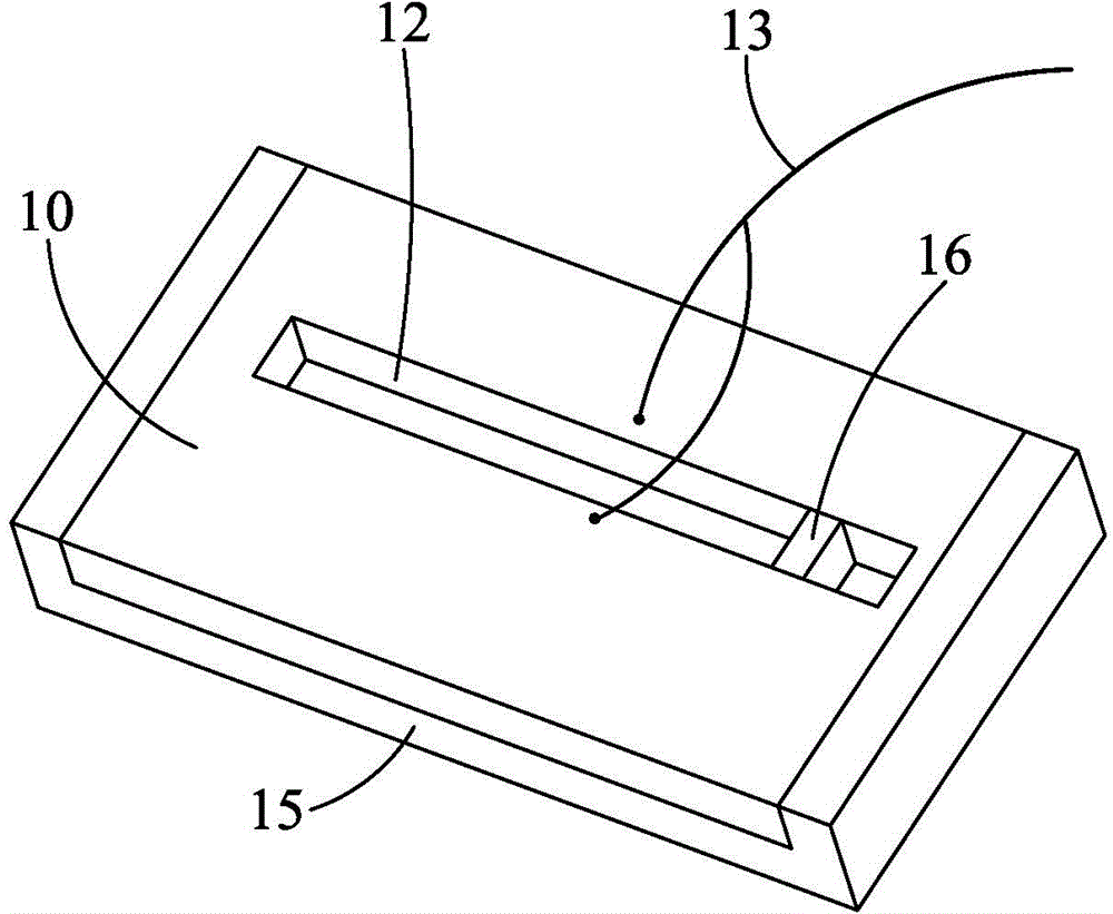
[0018] The slot antenna 10 of the present invention adopts ETS (Etching for Three-dimensional Structures, three-dimensional etching technology) or LDS (Laser Direct Structuring, laser direct structuring technology) process to make a metal cavity 12, and then feeds the signal into the Finally, the slot antenna 10 combines the bad hole slot 12, that is, the metal cavity 12, with the appearance of the mobile device 20 to reduce the abruptness of the appearance change to the user, and at the same time meet the design concept of the slot antenna 10 and the product appearance design requirements.

[0019] The design steps of slot antenna 10 of the present invention are as follows:

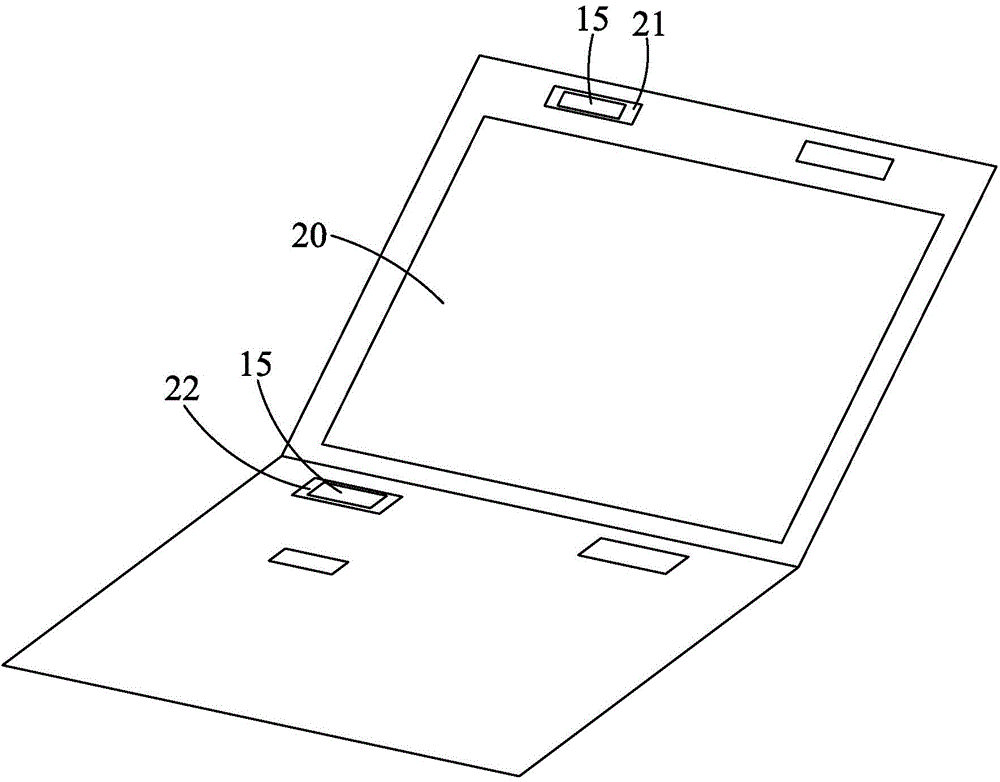
[0020] The first step is to find a suitable mobile device 20, such as a notebook computer, a mobile phone, a tablet computer, etc., whose external parts are made of metal, and use the original bad hole structure of the mobile device 20: plastic plugging hole 21 (Stopper Rubber Hole) and speakers The hole...


PUM


Abstract

The invention relates to a slot antenna. A metal cavity is formed in a plastic block by the adoption of an ETS or LDS manufacturing procedure, and the plastic block is arranged in a slot preformed in a mobile device. According to the slot antenna, the slot serves as a radiation bore, and the requirement for metallization of the appearance of the mobile device is met.

Description

technical field [0001] The invention relates to a slot antenna, in particular to a slot antenna arranged on a metal body and a design method thereof. Background technique [0002] In order to highlight the noble and elegant appearance of the mobile device (Handheld device or notebook), as well as the lightness and firmness of the structure, the metal body design has become a fashion trend, and the use of the metal body as the antenna structure is also the direction pursued by the industry. [0003] However, the metal body has a shielding effect on the radiation performance of the wireless signal, resulting in strong damage to the signal receiving and transmitting capabilities of the mobile device, and the design of the slot antenna is the main direction to solve this problem. [0004] The traditional combination of metal body and slot antenna has the following methods: [0005] The coaxial line feed-in method is to directly perform "broken hole action" on the metal body to ...

Claims


Application Information

Patent Timeline
Patent Type & Authority Applications(China)
IPC IPC(8): H01Q1/36H01Q13/10
Inventor 甘世宗汤庆仲张家齐
Owner KUNSHAN LIANTAO ELECTRONICS CO LTD
Why Eureka
Try Eureka