Automatic locking method for flexible direct-current transmission system

A flexible DC and power transmission system technology, applied in the direction of information technology support systems, electrical components, circuit devices, etc., can solve problems such as increasing the risk of tripping, misoperation of the control and protection system, prolonging the system locking process, etc., to shorten the locking process, The effect of improving reliability and reducing complexity

Active Publication Date: 2014-10-08
STATE GRID CORP OF CHINA +2
View PDF4 Cites 6 Cited by
  • Summary
  • Abstract
  • Description
  • Claims
  • Application Information

AI Technical Summary

Problems solved by technology

[0002] In the existing flexible DC transmission projects, regardless of the double-terminal flexible DC transmission project or the multi-terminal flexible DC transmission project, it is impossible to automatically realize the blocking of the entire flexible DC transmission system
Each converter station is responsible for the lockout process of the converter station at its own end. Under the unified deployment of dispatching, each converter station is locked in turn, which inevitably prolongs the lockout process of the entire system, and increases the tripping of individual converter stations during the system lockout process. trip risk
At the same time, in the whole blocking process, human factors play a dominant role, which may cause the fixed voltage control converter station to be blocked before the constant active power control converter station in the flexible DC system, resulting in malfunction of the control and protection system and affecting the stable operation of the AC and DC system.

Method used


Image

  • Automatic locking method for flexible direct-current transmission system
  • Automatic locking method for flexible direct-current transmission system
  • Automatic locking method for flexible direct-current transmission system

Examples


Embodiment Construction

[0018] The present invention will be further introduced below in conjunction with the drawings and specific embodiments.

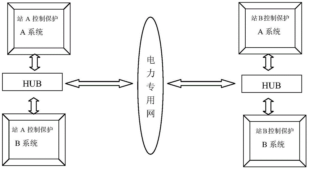
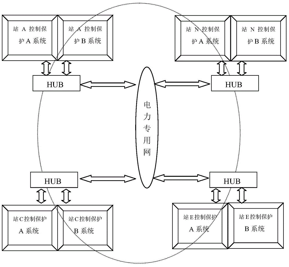
[0019] Such as figure 1 with figure 2 Shown are the associated structures of the control and protection systems of double-ended and multi-terminal flexible DC transmission systems. From the figure, it can be seen that the control and protection systems corresponding to each converter station are redundant systems regardless of whether it is double-ended or multi-terminal. During normal operation, the control and protection system operates in the active / standby mode. If the current main control system fails, the standby system in the hot standby state is automatically converted to the active system, and the entire system switching process will not disturb the DC power transmission. The control and protection system adopts two out of one protection and trip exit logic. The two sets of control and protection systems are independent of each other. Each protection...


PUM


Abstract

The invention discloses an automatic locking method for a flexible direct-current transmission system. The automatic locking method includes the following steps of firstly, judging the control mode of a station; secondly, judging the current running state when the flexible direct-current system runs if the station is judged to have the active power control mode; thirdly, starting the locking process of the station according to a received system locking control instruction if all the conditions are met, and conducting power reduction control; fourthly, sending a locking window signal to complete the locking process if both the active power and the reactive power of the current converter station are zero. By means of the automatic locking method for the flexible direct-current transmission system, a control and protection system in a flexible direct-current transmission project is automatically locked, the locking process of the flexible direct-current transmission system is shortened, impact which is caused by control and protection system incorrect operation generated due to man-made incorrect operation and the like to an alternating-current system is effectively avoided, time consumption of the whole locking process of the flexible direct-current system is lowered, the complexity in the locking process is lowered, and running reliability of a direct-current power grid is improved.

Description

Technical field [0001] The invention belongs to the field of flexible direct current transmission, and specifically relates to an automatic locking method of a flexible direct current transmission system. Background technique [0002] In the existing flexible DC transmission projects, no matter whether the double-terminal flexible DC project or the multi-terminal flexible DC transmission project, the entire flexible DC transmission system cannot be automatically locked. Each converter station is responsible for the blocking process of the local converter station. Under the unified deployment of dispatching, each converter station is locked in turn, which inevitably prolongs the entire system lock-up process, and increases the system lock-up process due to individual converter station tripping causing the entire system Risk of tripping. At the same time, in the entire blocking process, human factors dominate, which may cause the constant voltage control converter station in the f...

Claims


Application Information

Patent Timeline
Patent Type & Authority Applications(China)
IPC IPC(8): H02J13/00H02H7/26
CPCY02E60/00Y04S10/20
Inventor 康建爽郝俊芳曹森张爱玲孙宝丹吴庆范孔令凯王柏恒
Owner STATE GRID CORP OF CHINA
Why Eureka
Try Eureka