Eureka AIR delivers breakthrough ideas for toughest innovation challenges, trusted by R&D personnel around the world.

Novel milling cutter

A milling cutter and a new type of technology, applied in milling cutters, milling machine equipment, manufacturing tools, etc., can solve the problems of shortened tool service life, easy chip sticking at the end of the cutter teeth, and high manufacturing cost, and can improve the processing speed and facilitate chip removal. Reliable, low-cost manufacturing results

Inactive Publication Date: 2014-10-15
NANJING HAOWEI MACHINERY
View PDF0 Cites 0 Cited by
  • Summary
  • Abstract
  • Description
  • Claims
  • Application Information

AI Technical Summary

Problems solved by technology

[0003] At present, most of the milling cutters have a single function. During the machining process, the chip removal of the blade is not smooth, and the end edge of the cutter tooth is easy to stick chips, which leads to increased tool wear, reduced cutting ability, and shortened service life.
In addition, because of the use of bolts, it is necessary to sink holes in the base. The processing speed of existing tools for counterbore holes is often slow, the efficiency is not high, and the left and right torques are large, resulting in shortened tool life.
Chamfer milling cutters are used to mill chamfers. For the processing of ordinary aluminum alloy materials, the commonly used high-precision, high-speed chamfering milling cutters have complex structures and high manufacturing costs, which do not meet the actual use requirements.

Method used


Image

  • Novel milling cutter
  • Novel milling cutter

Examples


Embodiment Construction

[0016] The present invention will be further described below by means of the accompanying drawings and examples.

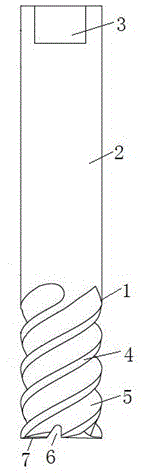
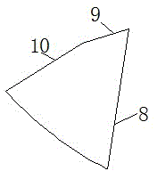
[0017] like figure 1 and figure 2 As shown, a novel milling cutter according to the present invention includes a cutter body 1, and a handle 2 connected to the cutter body 1, and an oil supply groove hole 3 is arranged on the upper part of the handle 2, and they are integrally formed. The cutter body 1 is composed of four sets of helical blades 4 and four sets of helical chip removal grooves 5, the helical blades 4 and the helical chip removal grooves 5 are evenly spaced, and the front parts of the two helical blades 4 on the same horizontal line are provided with Groove 6 is provided with chamfering teeth 7 at the other two helical blades 4 fronts, and described chamfering teeth 7 comprises first angle 8, is arranged on the second angle 9 besides first angle 8, and is arranged on the second The third angle 10 next to the angle 9, the first angle 8 is 10°, the ...


PUM


Abstract

The invention aims to overcome the defects in the prior art, and provides a novel milling cutter having the advantages of reasonable structure, convenience for chip removal, quick processing speed, low production cost and long service life. Compared with the prior art, the novel milling cutter has the prominent advantages of reasonable structure, convenience for processing and lower production cost; a groove is formed in an end edge, so that iron chips can be fed in a chip removing groove through the groove, the chip removal is convenient and reliable, and the chip bonding phenomenon is not occurred; as chamfered teeth consisting of a first angle, a second angle and a third angle are adopted, the structure of a chamfered milling cutter is simplified, and the processing speed is increased; and the novel milling cutter has a long service life, and can satisfy the actual use requirements.

Description

technical field [0001] The invention relates to a cutting tool, in particular to a milling cutter. [0002] Background technique [0003] At present, most milling cutters have a single function. During the machining process, the chip removal of the blade is not smooth, and the end edge of the cutter tooth is easy to stick chips, which leads to increased tool wear, reduced cutting ability, and shortened service life. In addition, due to the use of bolts, it is necessary to counterbore the base. The processing speed of existing tools for counterbore is often slow, the efficiency is not high, and the left and right torques are large, resulting in shortened service life of the tool. Chamfer milling cutters are used to mill out chamfers. For the processing of ordinary aluminum alloy materials, the commonly used high-precision, high-speed chamfer milling cutters have complex structures, high manufacturing costs, and do not meet the actual use requirements. [0004] Contents of...

Claims


Application Information

Patent Timeline
Patent Type & Authority Applications(China)
IPC IPC(8): B23C5/10
Inventor 于灿其
Owner NANJING HAOWEI MACHINERY
Why Eureka
Eureka Blog
Learn More