
Vehicle braking system and method

A technology of brake pipes and brakes, applied in the direction of brakes, charging systems, vehicle components, etc., can solve problems such as vehicle image degradation, achieve effective operation and improve driving experience

Inactive Publication Date: 2019-06-21
FORD GLOBAL TECH LLC
View PDF6 Cites 0 Cited by
  • Summary
  • Abstract
  • Description
  • Claims
  • Application Information

AI Technical Summary

Problems solved by technology

These conditions can degrade the personal driving experience as well as the impression of the vehicle

Method used


Image

  • Vehicle braking system and method
  • Vehicle braking system and method
  • Vehicle braking system and method

Examples


Embodiment Construction

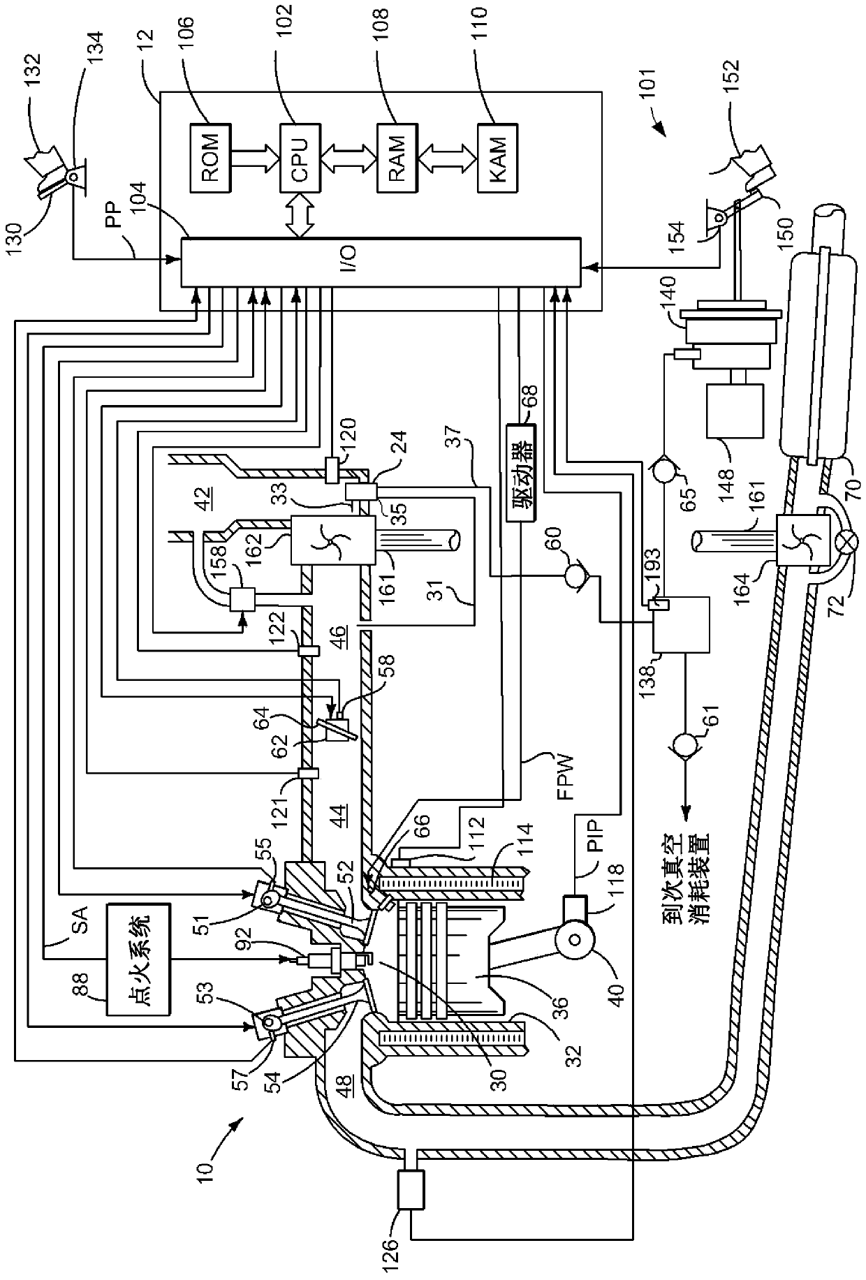
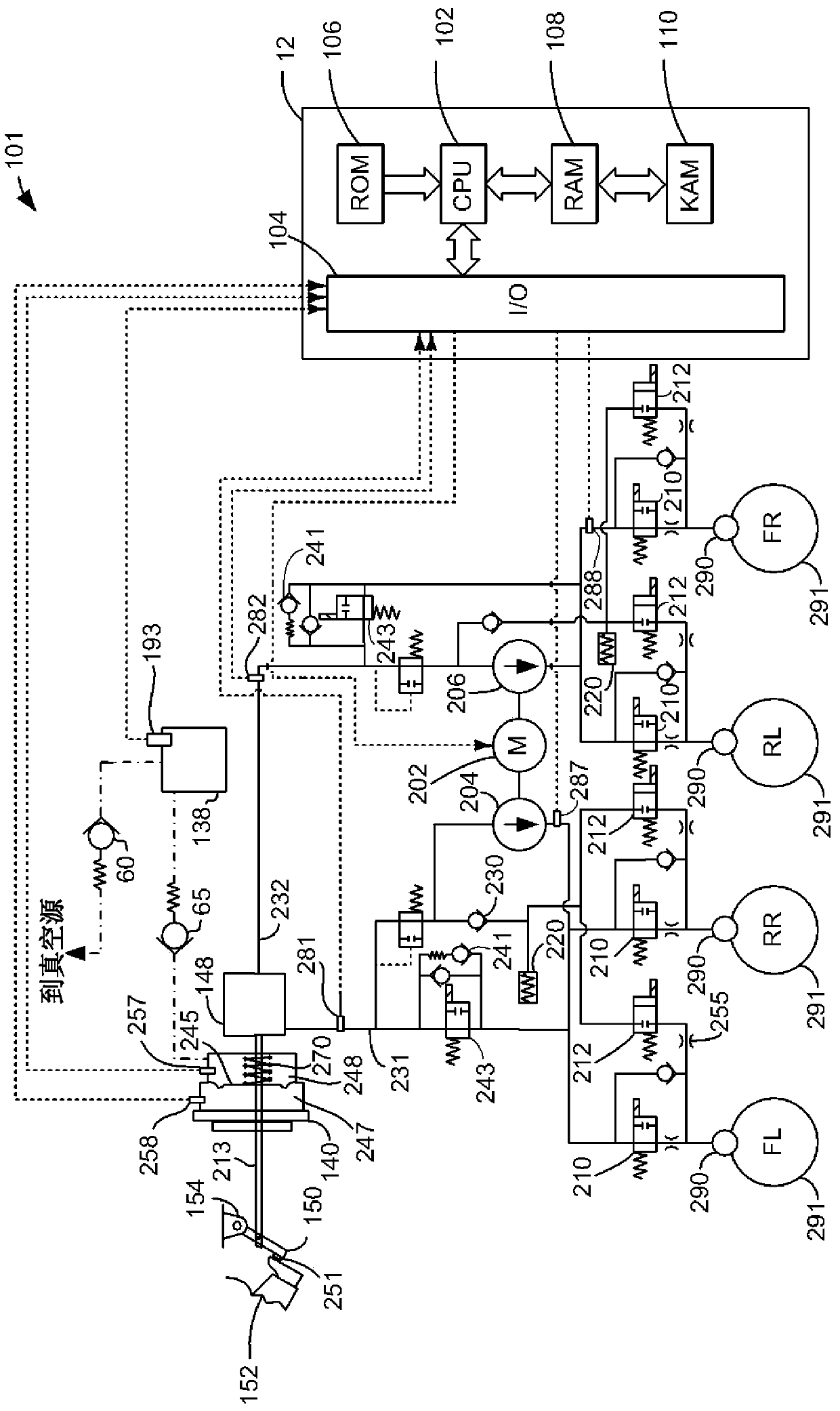
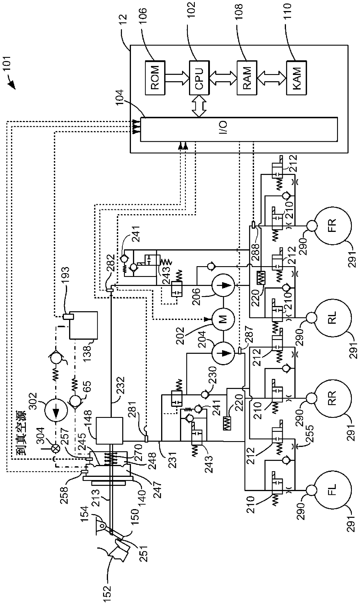
[0025] The present invention relates to improving vehicle brake operation. figure 1 An example system for providing vacuum to a vehicle is shown. figure 2 and 3 A more detailed view of an example vehicle braking system is shown. Figure 4 A graph showing the operating characteristics of a prior art method for applying the brakes of a vehicle. Figure 5 A curve is shown for the operating characteristics of the method for applying the brakes of the vehicle. Finally, in Image 6 A method for applying the brakes of a vehicle is shown in .

[0026] refer to figure 1 , the internal combustion engine 10 is controlled by an electronic engine controller 12, wherein the engine 10 comprises a plurality of cylinders, in figure 1 One of the cylinders is shown in . Engine 10 includes combustion chamber 30 and cylinder walls 32 with piston 36 disposed therein and coupled to crankshaft 40 . Combustion chamber 30 is shown communicating with intake manifold 44 and exhaust manifold 48 v...


PUM


Abstract

The present invention introduces systems and methods for increasing brake line pressure after brake booster vacuum has been depleted. In one example, after brake booster vacuum is depleted, brake line pressure is increased at the same rate as before brake booster vacuum is depleted.

Description

technical field [0001] The present application relates to a vehicle braking system and method. Background technique [0002] Vacuum may be used to assist the driver in applying the vehicle brakes. The vacuum acts on a diaphragm that helps move a rod connected to the brake pedal, and which increases the hydraulic pressure in the brake lines acting on the vehicle's brakes. The vacuum acts as a force on the area of ​​the diaphragm to assist the driver in applying the brakes. So, if the vacuum is a deeper vacuum (eg, lower pressure), the extra force acts on the diaphragm and assists the driver. Therefore, the braking force increases as the amount of vacuum increases. [0003] However, engine displacement is reduced to lower fuel consumption. Smaller displacement engines will have lower friction losses, and they will run more frequently at part throttle with fewer pumping losses than larger displacement engines. However, it is difficult to provide lower vacuum levels and gre...

Claims


Application Information

Patent Timeline
Patent Type & Authority Patents(China)
IPC IPC(8): B60T13/60
CPCB60T2201/03B60T8/442B60T17/02F02M35/10229F02D2250/41B60T8/17B60T13/58
Inventor R·W·坎宁哈姆R·D·珀西富尔
Owner FORD GLOBAL TECH LLC
Features
  • Generate Ideas
  • Intellectual Property
  • Life Sciences
  • Materials
  • Tech Scout
  • Unparalleled Data Quality
  • Higher Quality Content
  • 60% Fewer Hallucinations
Learn More