Selective catalytic reduction system of solid reductant

A reducing agent and selective technology, applied in mechanical equipment, engine components, machines/engines, etc., can solve problems such as uncontrollable urea purity, easy solidification of urea solution, and insufficient urea decomposition temperature

Active Publication Date: 2014-10-15
科林蓝泰环境科技(长春)有限公司
View PDF7 Cites 5 Cited by
  • Summary
  • Abstract
  • Description
  • Claims
  • Application Information

AI Technical Summary

Problems solved by technology

However, this technology has many shortcomings at the same time (such as low-temperature freezing of liquid urea, nozzle blockage, pipeline crystallization blockage, uncontrollable urea purity, etc.), specifically:
[0004] 1. Using urea aqueous solution as the reducing agent, when dealing with different working conditions, the urea solution sometimes decomposes excessively, which leads to the surplus of ammonia gas in the process of tail gas reduction and conversion, resulting in waste of resources
[0005] 2. Using urea aqueous solution as a reducing agent, sometimes the decomposition temperature of urea is not enough, which leads to the deposition of undecomposed urea at the nozzle opening. When the high-temperature exhaust gas flows through the nozzle opening, a chemical reaction will occur, forming crystals that are not easy to decompose, causing nozzle blockage
[0006] 3. Use urea aqueous solution as the reducing agent. When the urea aqueous solution is not decomposed enough, urea is easy to deposit in the jet pump. If the long-term deposition cannot be cleaned up, the jet pump will be damaged.
[0007] 4. Using urea aqueous solution as the reducing agent, when the temperature is below -11°, the urea solution is prone to solidification, which will cause the system to fail to operate normally
[0008] 5. For the SCR system, the urea solution is used, and the cruising range of the vehicle is shorter

Method used


Image

  • Selective catalytic reduction system of solid reductant

Examples


Embodiment Construction

[0026] In order to make the objectives, technical solutions, and advantages of the embodiments of the present invention clearer, the technical solutions in the embodiments of the present invention will be described clearly and completely in conjunction with the accompanying drawings in the embodiments of the present invention. Obviously, the described embodiments It is a part of the embodiments of the present invention, not all the embodiments. Based on the embodiments of the present invention, all other embodiments obtained by those of ordinary skill in the art without creative work shall fall within the protection scope of the present invention.

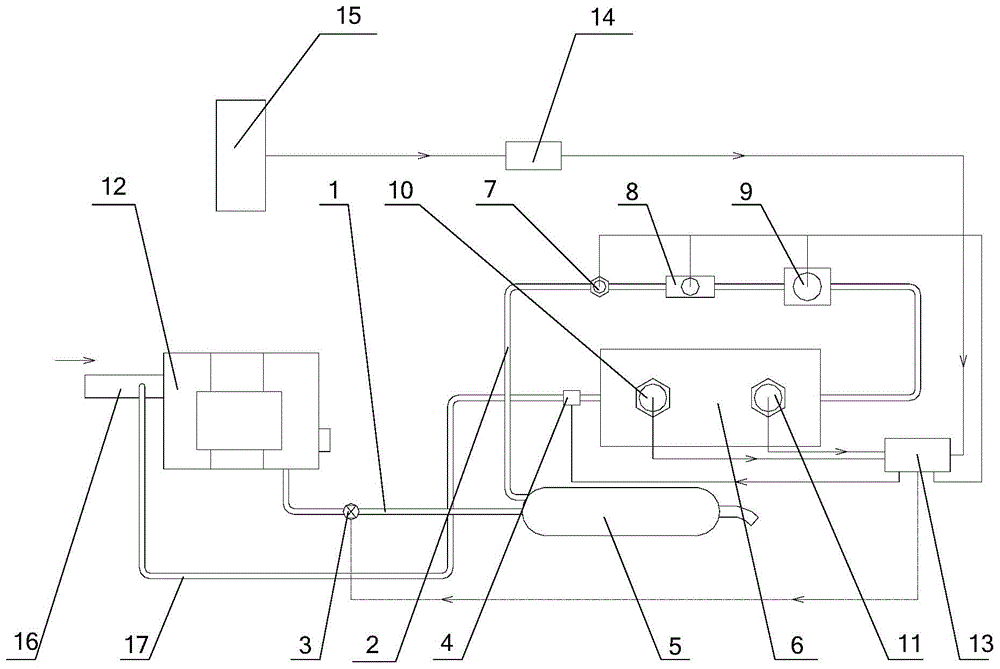
[0027] Please refer to figure 1 , figure 1 It is a schematic structural diagram of a solid reductant selective catalytic reduction system provided by an embodiment of the present invention.

[0028] The solid reductant selective catalytic reduction system provided by the embodiment of the present invention includes an exhaust gas proc...


PUM


Abstract

The invention discloses a selective catalytic reduction system of a solid reductant. The system comprises an exhaust gas treatment device, a controller, a solid ammonia storing device, a gasometer, a first switch and a second switch; the solid ammonia storing device is communicated with the exhaust gas treatment device through a first pipeline and communicated with the gasometer through a second pipeline; the gasometer is communicated with an exhaust gas conveying pipe through a third pipeline; the exhaust gas conveying pipe conveys the exhaust gas to the exhaust gas treatment device; the first switch is arranged on the first pipeline; the second switch is arranged on the third pipeline; the controller is connected with the first switch and the second switch. With the adoption of the selective catalytic reduction system of the solid reductant, the ammonia can be provided smoothly.

Description

Technical field [0001] The present invention relates to the technical field of tail gas treatment, in particular to a solid reductant selective catalytic reduction system. Background technique [0002] In recent years, air pollution has become more and more serious. Nearly 70% of the pollution sources are harmful substances such as soot particles, carbon monoxide, hydrocarbons, and nitrogen oxides emitted by motor vehicle exhaust. Most countries in Europe are already implementing the Euro IV emission standards, and our country has also put air pollution control as the top priority of current work. Therefore, the technology to meet the standards (National Four Standards) for vehicle exhaust emissions is also a major issue in the field of environmental protection. A technology for processing motor vehicle exhaust requires a reducing agent. After it is fully mixed with engine exhaust, a catalytic reduction reaction occurs through a carrier containing a catalyst to achieve the purpo...

Claims


Application Information

Patent Timeline
Patent Type & Authority Applications(China)
IPC IPC(8): F01N3/20
CPCY02A50/20Y02T10/12
Inventor 刘洪宝张柏禹唐守军刘庆国孙洪雷邢昌林刘泽
Owner 科林蓝泰环境科技(长春)有限公司
Why Eureka
Try Eureka