
Ceiling fan

A ceiling fan and a suspension rod technology, applied in the field of ceiling fans, can solve the problems of scattered electronic components of the ceiling fan, lack of humanization in use, inconvenient production and assembly, etc., and achieve the effect of convenient and reasonable assembly structure setting, favorable assembly, and beautiful appearance.

Inactive Publication Date: 2014-10-15
ZHONGSHAN WEIHE ELECTRICAL APPLIANCES
View PDF0 Cites 1 Cited by
  • Summary
  • Abstract
  • Description
  • Claims
  • Application Information

AI Technical Summary

Problems solved by technology

The fan blades of the ceiling fan are driven by the motor to make the surrounding air flow to generate wind, and the wind speed is determined by the speed of the fan blade rotation speed. The common ceiling fans on the market today generally use patch-type permanent magnet DC motors and use remote control. The control method is used to control the ceiling fan, and the circuit part of the motor, the remote control receiving part and other related functional circuits are usually independently and scattered in the ceiling fan, which will make the electronic components of the ceiling fan scattered and not concentrated, and the production and assembly are inconvenient. Difficult, lack of reliability, high cost, and not humane enough in use, it can be seen that there is a need for further improvement

Method used


Image

  • Ceiling fan
  • Ceiling fan
  • Ceiling fan

Examples


Embodiment Construction

[0018] In order to make the objectives, technical solutions and advantages of the present invention clearer, the present invention will be further described in detail below with reference to the accompanying drawings and embodiments. It should be understood that the specific embodiments described herein are only used to explain the present invention, but not to limit the present invention.

[0019] The specific implementation of the present invention is described in detail below in conjunction with specific embodiments:

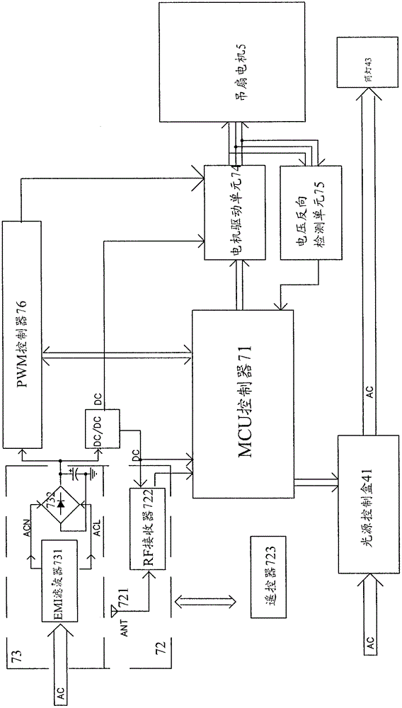
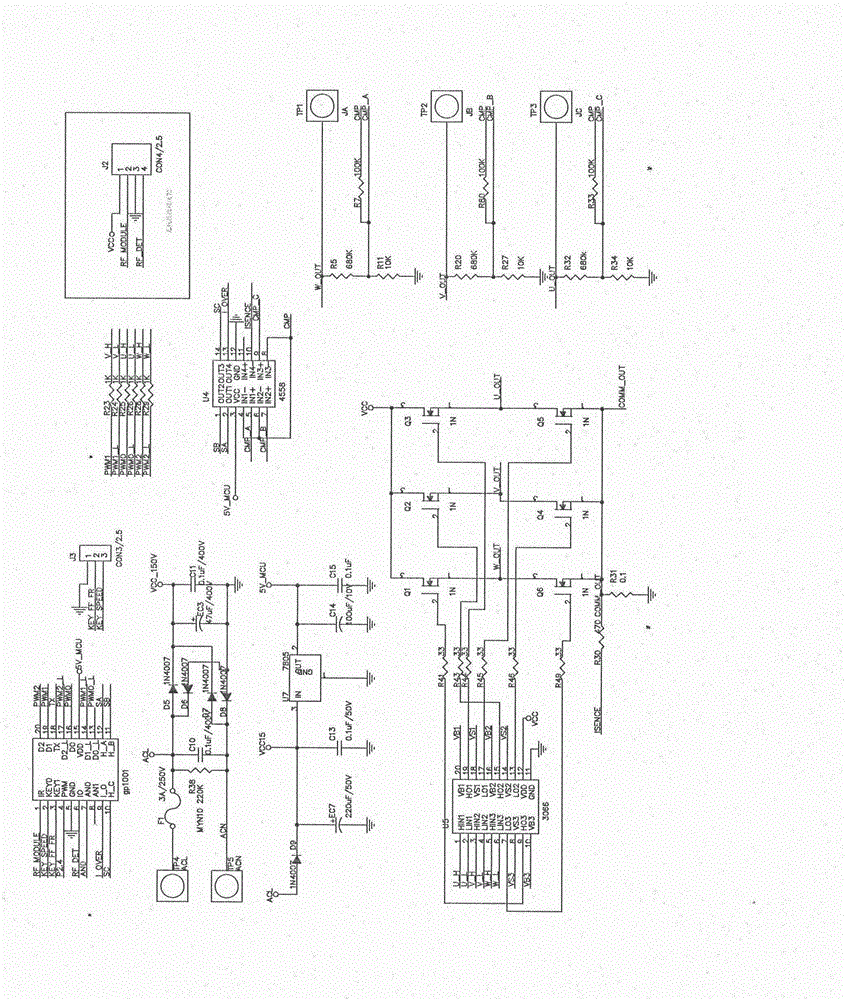
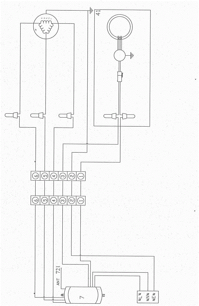
[0020] refer to Figure 4 , a ceiling fan provided by the present invention, its main structure includes a hanger 1, a hanger rod 2, a hanging cup 3, a cover body 4, a motor 5, a fan blade 6 and a ceiling fan controller 7, wherein such as figure 1 As shown, the main components of the ceiling fan controller include an MCU controller 71, a wireless receiving unit 72, a rectification filter unit 73, a DC / DC converter 73, a motor drive unit 74, a voltage reverse...


PUM


Abstract

The invention discloses a ceiling fan which comprises a hanging bracket, a hanging rod, a hanging handleless cup, a cover body, a motor, fan blades and a ceiling fan controller, wherein the ceiling fane controller comprises an MCU (Microprogrammed Control Unit), a wireless receiving unit, a rectification filtration unit, a DC / DC (Direct Current / Direct Current) converter, a motor driving unit, a voltage reversal detection unit and a PWM (Pulse-Width Modulation) controller, wherein the MCU is respectively connected with the wireless receiving module, the motor driving unit, the voltage reversal detection unit and the PWM controller; the MCU controller receives a control signal from the ceiling fan controller by virtue of the wireless receiving unit; the motor driving unit is connected with the motor and is capable of driving the motor; the voltage reversal detection unit is connected with the motor and is capable of feeding back a signal to the MCU; the rectification filtration unit is connected with the DC / DC converter and the PWM controller; the DC / DC converter is respectively connected with the MCU, the wireless receiving unit and the motor driving unit so as to perform operation power supply; the PWM controller is capable of supplying power to the motor by virtue of the motor driving unit.

Description

technical field [0001] The present invention relates to a ceiling fan. Background technique [0002] The ceiling fan can be hung on the ceiling to supply air to the indoor environment. It is a product with good heat-relieving function, energy saving and power saving, as well as decorative effect, and is very popular in the market. The fan blades of the ceiling fan are driven by the motor to make the surrounding air flow to generate wind, and the wind speed is determined by the speed of the fan blade rotation speed. At present, the common ceiling fans on the market generally use SMD permanent magnet DC motors, which use remote control. The control method is used to control the ceiling fan, and the circuit part of the motor, the remote control receiving part and other related functional circuits are usually independent and scattered in the ceiling fan. It is difficult, and the reliability is insufficient, and the cost is high, and the use is not humane enough. It can be seen ...

Claims


Application Information

Patent Timeline
IPC IPC(8): F04D27/00F04D29/60
Inventor 卢骏
Owner ZHONGSHAN WEIHE ELECTRICAL APPLIANCES
Learn More