A dynamic balance detection method for multi-disc rotors based on rotating coordinate system

A technology of rotating coordinate system and rotor dynamic balance, which is used in static/dynamic balance testing, machine/structural component testing, measuring devices, etc. It can solve the problems of not considering the elastic deformation of the rotating shaft, limited sampling frequency, and low efficiency.

Active Publication Date: 2017-05-24
SOUTHEAST UNIV
View PDF5 Cites 2 Cited by
  • Summary
  • Abstract
  • Description
  • Claims
  • Application Information

AI Technical Summary

Problems solved by technology

This method is widely used in engineering, but it has the following disadvantages: (1) The influence coefficient needs to be obtained through experiments, and the unit needs to be started and stopped repeatedly, and the efficiency is low
This method has the following disadvantages: (1) the rotor is regarded as a rigid rotor, and the elastic deformation of the rotating shaft is not considered; (2) the unbalanced force is equivalent to two planes, and the weighted surface and the unbalanced surface are often not on the same plane; (3) It needs to be equipped with a special dynamic balancing machine, which has higher requirements for testing equipment
At this stage, the sampling frequency of wireless testers is limited, the highest is only 1KHz

Method used


Image

  • A dynamic balance detection method for multi-disc rotors based on rotating coordinate system
  • A dynamic balance detection method for multi-disc rotors based on rotating coordinate system
  • A dynamic balance detection method for multi-disc rotors based on rotating coordinate system

Examples


Embodiment Construction

[0066] Further explain the present invention below in conjunction with accompanying drawing.

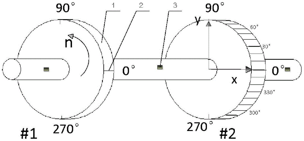
[0067] This example is for figure 1 The shaft system shown in the experiment is carried out, and the double disc is taken as an example to provide a multi-disc rotor dynamic balance detection method based on the rotating coordinate system. refer to Figure 2-4 .

[0068] Such as Figure 4 As shown in the flow chart, the method for detecting the dynamic balance of a multi-disc rotor in a rotating coordinate system according to this embodiment includes the following steps:

[0069] A. Install the rotating shaft to be tested on the test stand;

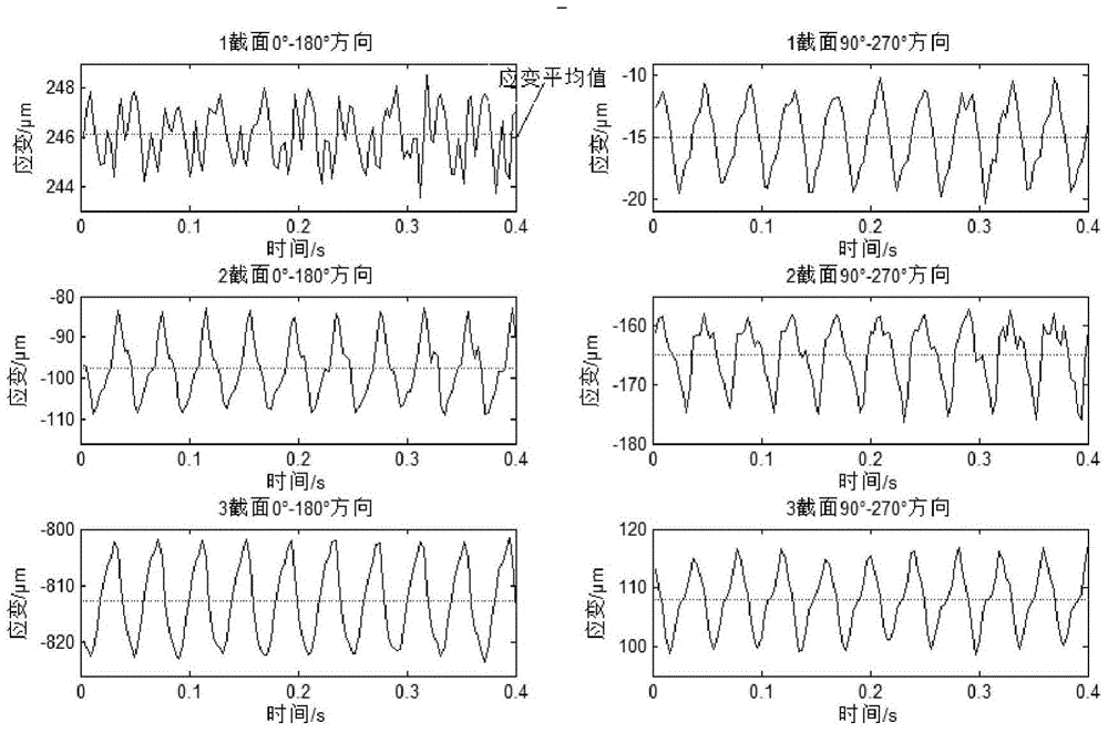
[0070] B. Strain sensors are arranged on both sides of the rotating shaft to be identified. Taking the two roulette models shown in the figure as an example, it is necessary to select three sections at both ends of the roulette, and arrange a set of strain sensors in the directions of 0°-180° and 90°-270°, each with 3 sections, and a total ...


PUM


Abstract

The invention discloses a multi-wheel-disc rotor dynamic balancing test method based on a rotating coordinate system. The method includes calibrating an angular coordinate on a wheel disc, and arranging strain sensors on the cross section of shafts on both sides of the wheel disc of a rotor; respectively recording strain values of the wheel disc in the corresponding direction under different stress in two perpendicular direction, and respectively calibrating direction coefficients of the relationship between the strain and force in the two direction; starting a motor to provide a given balancing speed n, and measuring an average value of the strain in the two perpendicular direction of the cross section in the rotating coordinate system; calculating the magnitude of the unbalanced force on the wheel disc and the phase through the obtained average value of the strain and the direction coefficients in the two perpendicular direction, wherein the phase can be directly read out through the rotating coordinate system; obtaining the weight m weighted on the wheel disc and the phase theta through the obtained unbalanced force, the given balancing speed n and the given weighting radius r. The multi-wheel-disc rotor dynamic balancing test method based on the rotating coordinate system can be used for testing without a key phase sensor and data acquisition synchronization of measuring points, thereby greatly reducing the requirement on sampling rate of a data acquisition system.

Description

technical field [0001] The invention relates to the detection of rotating mechanical parts, in particular to a method for detecting the dynamic balance of a multi-disc rotor in a rotating coordinate system. Background technique [0002] Rotating machinery, such as steam turbines, generators, gas turbines, compressors, fans, pumps, etc., are key equipment in industries such as aviation, electric power, petrochemical, and metallurgy. Affected by factors such as rotor machining accuracy, assembly error, and thermal deformation, the center of mass of the rotating machinery parts does not coincide with the center of rotation, and an unbalanced excitation force will be generated in the rotating state, resulting in vibration of the unit and shortening the service life of the unit. Unbalanced faults are the most common vibration faults of various types of rotating machinery, accounting for more than 80% of all types of faults. It is of great engineering significance to improve the ...

Claims


Application Information

Patent Timeline
Patent Type & Authority Patents(China)
IPC IPC(8): G01M1/16
Inventor 杨建刚房久正
Owner SOUTHEAST UNIV
Why Eureka
Try Eureka