Ball-end cutter multi-axis machining cutter axis vector optimization method

A tool axis vector, multi-axis machining technology, applied in electrical program control, digital control and other directions, can solve the problems of impact, reduce surface machining quality and machining efficiency, tool axis vector fluctuation and mutation, etc., to avoid severe fluctuations, improve Machining efficiency and machining quality, smooth and smooth movement of machine axes

Active Publication Date: 2014-10-15
SHANDONG UNIV OF TECH
View PDF4 Cites 40 Cited by
  • Summary
  • Abstract
  • Description
  • Claims
  • Application Information

AI Technical Summary

Problems solved by technology

[0007] The tool positioning method of prior art 1 relies heavily on the geometric properties of the tool contact point on the design surface (such as the normal vector of the surface, the main direction, curvature, etc.). There may be large fluctuations and sudden changes in the axis vector, which will cause impact on the machine tool, exceed the limit of the speed and acceleration of the machine tool feed axis, etc., thereby reducing the surface processing quality and processing efficiency; while the existing technology 2 can avoid the sharp change of the tool axis vector However, it is necessary to re-designate a new tool axis vector according to the characteristics of the workpiece surface after each line or several lines are processed, otherwise it will cause interference between the tool and the workpiece surface, and reduce the surface processing quality and processing efficiency

Method used


Image

  • Ball-end cutter multi-axis machining cutter axis vector optimization method
  • Ball-end cutter multi-axis machining cutter axis vector optimization method
  • Ball-end cutter multi-axis machining cutter axis vector optimization method

Examples


Embodiment

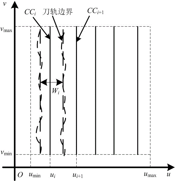
[0056] Embodiment: The method for generating the tool path for processing the inlet and outlet edges of blades is taken as an example below to further describe the method in detail.

[0057] By analyzing a given workpiece surface S : r ( u , v )( , ) to determine the cutting direction of the tool, and describe the arrangement of the tool contact track on the surface of the workpiece in the parameter field, such as Figure 4 shown. set tool edge v The tool moves in the direction of the parameter, and the processing range of the surface in the parameter domain is , u min with u max respectively represent the left and right boundaries of surface processing, v min with v max respectively represent the front and rear boundaries of surface processing; CC i on the surface i strip knife contact track, W i for the first i Toolpath S i The average row width of . suppose h For a given programming tolerance, It is the processing line width coefficient. ...


PUM


Abstract

The invention discloses a ball-end cutter multi-axis machining cutter axis vector optimization method. The method includes the following steps that: at first, a relationship equation between cutter location optimization variables and cutter location data is constructed, and at the same time, a movement transformation equation between the cutter location data and machine tool rotation axis angles is constructed, and therefore a relationship equation between the cutter location optimization variables and the machine tool rotation axis angles can be derived; then, a cutter axis vector computational formula of ball-end cutter multi-axis machining complex curved surfaces can be obtained through solving the above equations; and finally, the ball-end cutter multi-axis machining cutter axis vector optimization method is rendered based on the above steps. With the ball-end cutter multi-axis machining cutter axis vector optimization method adopted, large fluctuation of machine tool rotation axes in a machining process can be avoided, and the movement of the machine tool axes is more stable and smooth, and therefore, machining quality and machining efficiency of the curved surfaces can be improved. The ball-end cutter multi-axis machining cutter axis vector optimization method has a certain practical application value.

Description

Technical field [0001] The invention involves a programming method of a multi -axis CNC machine tool processing complex curved surface, especially a spherical polyxarial multi -axis processing knife axis vector optimization method, which belongs to the field of five -axis CNC machining machine tools. Background technique [0002] Aviation engine blades are key parts of aviation engines. The quality of processing quality will directly affect the working performance of the aviation engine, and the processing of the blade inlet and exhaust is a key factor affecting the quality of the entire blade processing. ThereforeProcessing plays a very important role in improving the quality of leaves.At present, in the actual production process of leaves, due to the poor geometry of the design curved surface (such as the legal vector, main direction, curvature, etc.) of the surface, the five -axis processing knife rail and the direction of the knife shaft will fluctuate, and even the direction...

Claims


Application Information

Patent Timeline
Patent Type & Authority Applications(China)
IPC IPC(8): G05B19/19
Inventor 徐汝锋赵维平陈志同郑光明程祥
Owner SHANDONG UNIV OF TECH
Why Eureka
Try Eureka