Side-lobe suppression based beam optimization method for electrical tilt parasitic antennas

A side lobe suppression, parasitic antenna technology, applied in electrical digital data processing, special data processing applications, instruments, etc., can solve the problem of difficult to accurately control the pattern shape

Active Publication Date: 2014-10-15
CHINA ELECTRONIS TECH INSTR CO LTD
View PDF3 Cites 10 Cited by
  • Summary
  • Abstract
  • Description
  • Claims
  • Application Information

AI Technical Summary

Problems solved by technology

[0053] Aiming at the problem of scanning the pattern of the electric-tunable parasitic antenna in the existing beam optimization method, the electric-tunable parasitic antenna needs to adjust the beam pointing by changing the loaded reactance value, and the shape of the pattern is difficult to control accurately.

Method used


Image

  • Side-lobe suppression based beam optimization method for electrical tilt parasitic antennas
  • Side-lobe suppression based beam optimization method for electrical tilt parasitic antennas
  • Side-lobe suppression based beam optimization method for electrical tilt parasitic antennas

Examples


Embodiment Construction

[0095] The following will clearly and completely describe the technical solutions in the embodiments of the present invention with reference to the accompanying drawings in the embodiments of the present invention. Obviously, the described embodiments are only some, not all, embodiments of the present invention. Based on the embodiments of the present invention, all other embodiments obtained by persons of ordinary skill in the art without making creative efforts belong to the protection scope of the present invention.

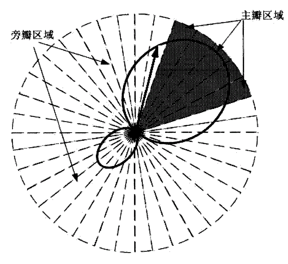
[0096] Although the existing beam optimization method can form the main lobe and few nulls in the desired direction, it is also easy to form relatively large side lobes in some directions. In the wireless propagation environment, due to the rich multipath effect, excessive Large side lobes tend to introduce some multipath and interference from other users.

[0097] In the present invention, side lobe suppression is also taken into consideration, which will gre...


PUM


Abstract

The invention provides a side-lobe suppression based beam optimization method for electrical tilt parasitic antennas. The method includes the steps of firstly, establishing an antenna array three-dimensional model according to a designed sign, calculating resonant frequencies of antennas and admittance features of antenna ports, introducing calculation results as known parameters of a side-lobe suppression algorithm into a side-lobe suppression algorithm program, and using an optimized result output after the side-lobe suppression algorithm program converges, as an impedance load value; performing further verification on the obtained load value, putting the optimized load value into ports of parasitic units, and calculating a directional diagram of the antennas. The side-lobe suppression based beam optimization method for the electrical tilt parasitic antennas has the advantages that side-lobe suppression is introduced in the optimization process as a second target function, suppression ratios of the main lobe relative to any side lobes are larger than a certain level, and multipath interference suppression can be improved on the premise of ensuring gain, main lobe formation and few nulls.

Description

technical field [0001] The invention relates to the technical field of antennas, in particular to a beam optimization method for electrically adjustable parasitic antennas based on sidelobe suppression. Background technique [0002] The electrically adjustable parasitic antenna was first proposed by Harrington et al. in the field of scanning arrays in the 1970s. Its structure is as follows figure 1 As shown, the array is composed of an active antenna unit and a reactance loading unit, and the scanning of the array pattern is realized by changing the reactance loading value of the parasitic unit. In the paper, Sinnolt et al. proposed the theoretical model of the electrically adjustable parasitic array antenna, and conducted a preliminary discussion on the beam optimization algorithm of the parasitic element loading reactance value. In the mid-1980s, Dinger continued to promote the development of this type of antenna, and made new contributions in beam optimization algorithms...

Claims


Application Information

Patent Timeline
IPC IPC(8): G06F17/50
Inventor 孙佳文
Owner CHINA ELECTRONIS TECH INSTR CO LTD
Why Eureka
Try Eureka