Device and method for positioning workpiece on linear conveyor belt through visual system

A vision system and positioning device technology, applied in the direction of conveyor control devices, conveyor objects, transportation and packaging, etc., can solve the problems of low compensation accuracy, large time loss, and the speed of the conveyor belt cannot be too fast, etc., to achieve high compensation accuracy , fast effect

Active Publication Date: 2014-10-22
SHANGHAI FANUC ROBOTICS
View PDF10 Cites 26 Cited by
  • Summary
  • Abstract
  • Description
  • Claims
  • Application Information

AI Technical Summary

Problems solved by technology

[0003] In view of this, the present invention proposes a device and method for positioning workpieces on a linear conveyor belt using a visual system to solve the above-mentioned problems of large time loss, low compensation accuracy, and the speed of the conveyor belt cannot be too fast

Method used


Image

  • Device and method for positioning workpiece on linear conveyor belt through visual system
  • Device and method for positioning workpiece on linear conveyor belt through visual system
  • Device and method for positioning workpiece on linear conveyor belt through visual system

Examples


Embodiment 1

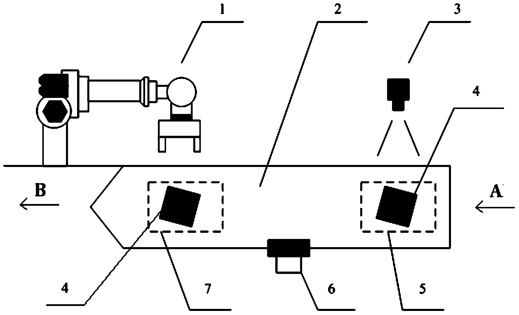
[0026] Please combine figure 1 As shown, a device and method for positioning a workpiece on a linear conveyor belt using a vision system according to the present invention includes a positioning device system and a positioning method,

[0027] The positioning device system includes: a vision system 3, a pulse encoder 6, a robot 1 and a linear conveyor belt 2, and the linear conveyor belt 2 has a shooting area 5 and a working area 7, and is characterized in that,

[0028] The positioning method is: place the workpiece 4 in the shooting area 5 and keep it still, the vision system 3 takes and records the position information of the workpiece 4 in the shooting area 5, and the linear conveyor belt 2 moves the workpiece 4 from the upstream direction A to the downstream direction B Carry out linear transmission and stop after a certain distance, the pulse encoder 6 detects the linear distance data generated after the linear conveyor belt 2 moves, and transmits the data to the robot 1...

Embodiment 2

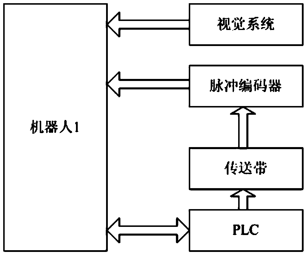
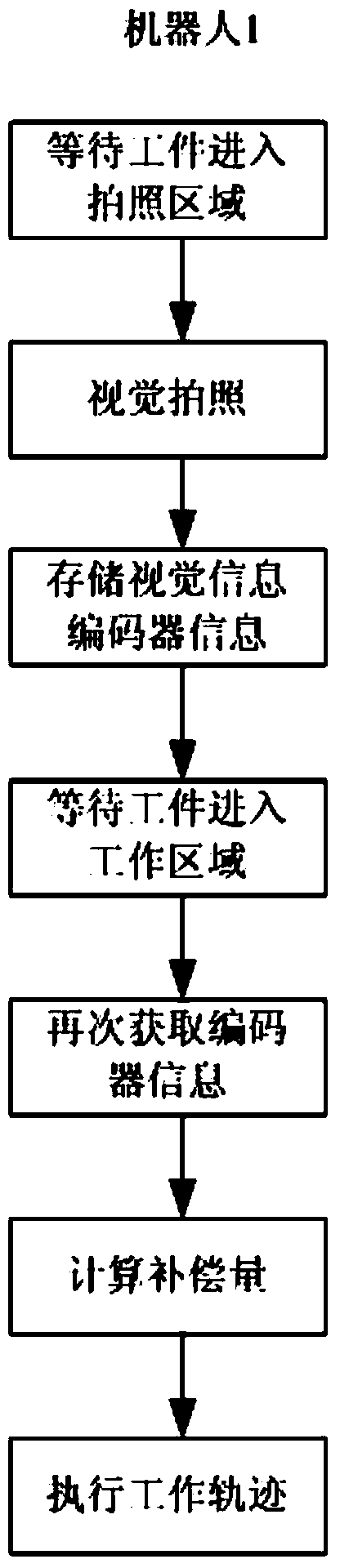
[0038] In this embodiment, the pulse encoder and the vision system are set on the same robot, please combine figure 2 and image 3 as shown,

[0039] When the vision system and the encoder are installed on the same robot, the PLC controls the work of the robot 1 by interacting with the signal of the robot 1, and at the same time directly drives the motion of the linear conveyor 2; the pulse encoder 6 obtains the position information of the linear conveyor 2, and together with The information of the vision system 3 is sent to the robot 1, and the robot 1 independently completes the functions of far-end shooting and near-end work trajectory compensation.

[0040] The specific implementation steps are: the specific layout structure in this embodiment is the same as that of Embodiment 1, except that the pulse coder and the vision system are all set on the same robot, so only the important points are described. When the vision system 3 and the pulse coder 6 When installed on the...

Embodiment 3

[0042] In this embodiment, the pulse encoder and vision system are set on two different robots, please combine Figure 4 and Figure 5 as shown,

[0043] When the vision system and the encoder are installed on two different robots, the PLC realizes their control by interacting with the signals of robot 1 and robot 2, and at the same time directly drives the movement of the linear conveyor belt 3; the pulse encoder 6 obtains the position information of the linear conveyor belt 2 and sends it into the Robot 1, and the information obtained by vision system 3 is sent to robot 2; robot 2 sends the data information obtained by vision system 3 to robot 1 through the local area communication network between robots; The position information and the visual information obtained from the robot 2 realize the functions of far-end shooting and near-end working trajectory compensation.

[0044] The specific implementation steps are: the specific layout structure in this embodiment is the sa...


PUM


Abstract

The invention discloses a device and method for positioning a workpiece on a linear conveyor belt through a visual system. The workpiece is placed in a photographing area to be fixed. A visual system photographs and records the position information of the workpiece in the photographing area, the linear conveyor belt conducts linear conveying on the workpiece from the upstream direction to the downstream direction, and the conveyor belt is stopped after conducting conveying for a distance. A pulse encoder detects linear distance data which are generated after the linear conveyor belt moves and transmits the data to a robot. The robot analyzes the data and works out the needed compensation amount for a work track, accurate positioning is achieved, and finally the robot acts on the workpiece. By means of the device and method for positioning the workpiece on the linear conveyor belt through the visual system, far-end visual positioning is used for near-end work track compensation, and compared with a dynamic linear tracking technology, compensation precision is high, and in addition the speed of the conveyor belt can be higher.

Description

technical field [0001] The invention relates to the technical field of robot automation, in particular to a device and method for positioning workpieces on a linear conveyor belt using a vision system. Background technique [0002] The general robot vision system is after the CCD camera takes a photo of the workpiece to obtain the position information, and then the robot performs trajectory compensation at the same position, that is, the position compensation data obtained by the visual photography is only valid for the current position of the workpiece, so the robot must be kept when executing the work trajectory. The location of the photo cannot be changed. The limitation of such robot vision technology is that at the same position, it must be carried out in strict accordance with the order of taking photos first and then working. Sometimes when there are multiple cameras near the installation position of the robot, the robot often cannot effectively avoid it to make room ...

Claims


Application Information

Patent Timeline
Patent Type & Authority Applications(China)
IPC IPC(8): B65G43/00
Inventor 杨恒亮王萌珏王鑫张晓荣
Owner SHANGHAI FANUC ROBOTICS
Why Eureka
Try Eureka