A device and method for positioning a workpiece on a linear conveyor belt using a vision system
A vision system and positioning method technology, which is applied to conveyor control devices, conveyor objects, transportation and packaging, etc., can solve the problems of low compensation accuracy, excessive time loss, and the speed of the conveyor belt cannot be too fast, and achieve high compensation accuracy. , fast effect
- Summary
- Abstract
- Description
- Claims
- Application Information
AI Technical Summary
Problems solved by technology
Method used
Image
Examples
Embodiment 1
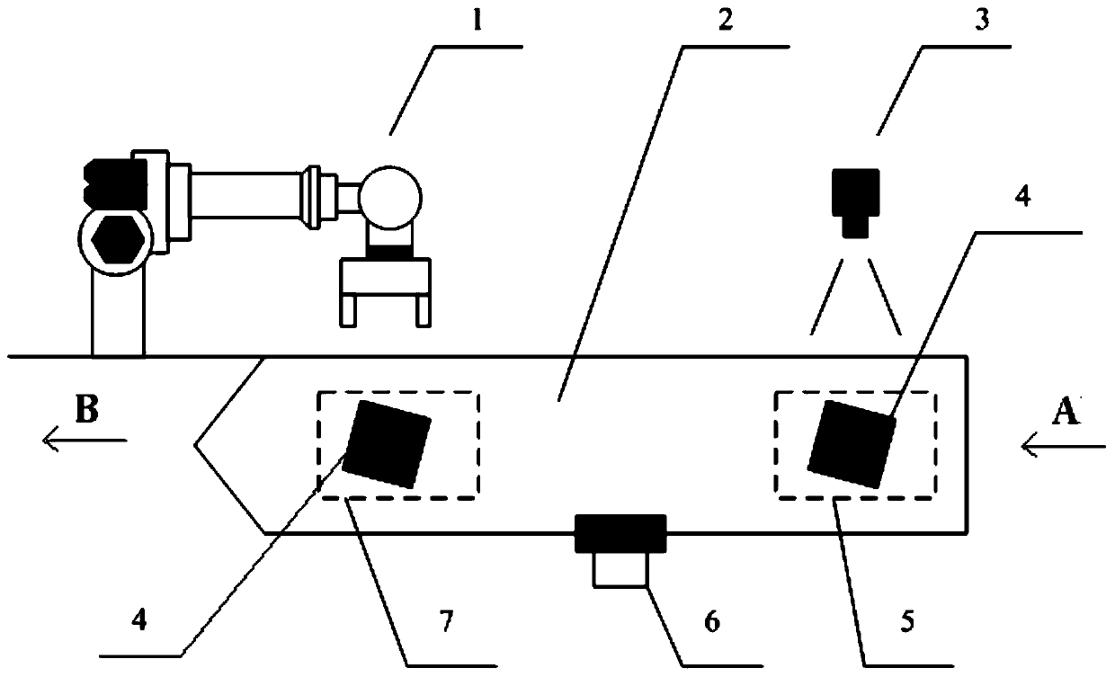
[0026] Please combine figure 1 As shown, a device and method for positioning a workpiece on a linear conveyor belt using a vision system according to the present invention includes a positioning device system and a positioning method,
[0027] The positioning device system includes: a vision system 3, a pulse encoder 6, a robot 1 and a linear conveyor belt 2, and the linear conveyor belt 2 has a shooting area 5 and a working area 7, and is characterized in that,
[0028] The positioning method is: place the workpiece 4 in the shooting area 5 and keep it still, the vision system 3 takes and records the position information of the workpiece 4 in the shooting area 5, and the linear conveyor belt 2 moves the workpiece 4 from the upstream direction A to the downstream direction B Carry out linear transmission and stop after a certain distance, the pulse encoder 6 detects the linear distance data generated after the linear conveyor belt 2 moves, and transmits the data to the robot 1...
Embodiment 2
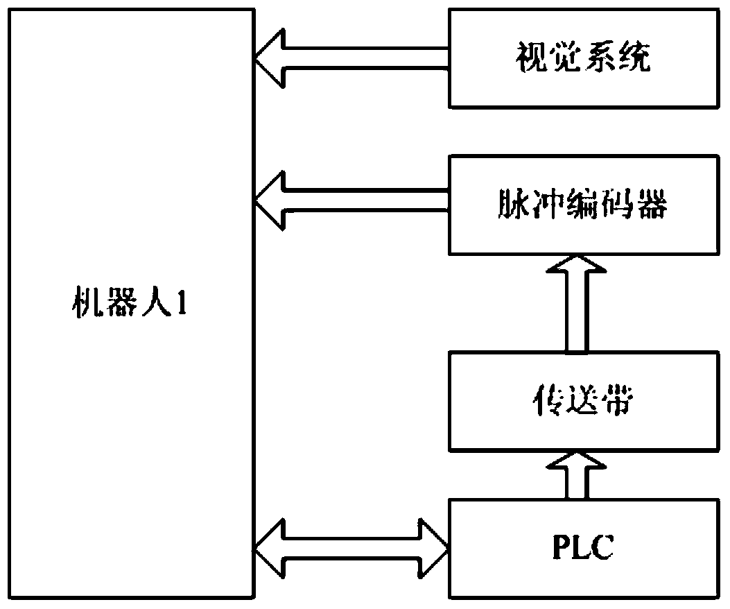
[0038] In this embodiment, the pulse encoder and the vision system are set on the same robot, please combine figure 2 and image 3 as shown,
[0039] When the vision system and the encoder are installed on the same robot, the PLC controls the work of the robot 1 by interacting with the signal of the robot 1, and at the same time directly drives the motion of the linear conveyor 2; the pulse encoder 6 obtains the position information of the linear conveyor 2, and together with The information of the vision system 3 is sent to the robot 1, and the robot 1 independently completes the functions of far-end shooting and near-end work trajectory compensation.
[0040] The specific implementation steps are: the specific layout structure in this embodiment is the same as that of Embodiment 1, except that the pulse coder and the vision system are all set on the same robot, so only the important points are described. When the vision system 3 and the pulse coder 6 When installed on the...
Embodiment 3
[0042] In this embodiment, the pulse encoder and vision system are set on two different robots, please combine Figure 4 and Figure 5 as shown,
[0043] When the vision system and the encoder are installed on two different robots, the PLC realizes their control by interacting with the signals of robot 1 and robot 2, and at the same time directly drives the movement of the linear conveyor belt 3; the pulse encoder 6 obtains the position information of the linear conveyor belt 2 and sends it into the Robot 1, and the information obtained by vision system 3 is sent to robot 2; robot 2 sends the data information obtained by vision system 3 to robot 1 through the local area communication network between robots; The position information and the visual information obtained from the robot 2 realize the functions of far-end shooting and near-end working trajectory compensation.
[0044] The specific implementation steps are: the specific layout structure in this embodiment is the sa...
PUM
 Abstract
Description
Claims
Application Information
 - R&D
- Intellectual Property
- Life Sciences
- Materials
- Tech Scout
- Unparalleled Data Quality
- Higher Quality Content
- 60% Fewer Hallucinations
Browse by: Latest US Patents, China's latest patents, Technical Efficacy Thesaurus, Application Domain, Technology Topic, Popular Technical Reports.
© 2025 PatSnap. All rights reserved.Legal|Privacy policy|Modern Slavery Act Transparency Statement|Sitemap|About US| Contact US: help@patsnap.com


