
Combined cycle engine

An engine and annular technology, which is applied in the direction of machines/engines, jet propulsion devices, etc., can solve the problems that the overall performance cannot be further improved, the technical requirements of turbine engines are demanding, and the components are complex, so as to improve combustion efficiency and space combustion utilization. , improve thermodynamic efficiency and simplify the structure

Active Publication Date: 2014-10-22
清航空天(浙江)科技有限公司
View PDF6 Cites 18 Cited by
  • Summary
  • Abstract
  • Description
  • Claims
  • Application Information

AI Technical Summary

Problems solved by technology

However, in the process of actual engineering use, the turbo-ramjet combined cycle engine is subject to great development restrictions due to the complexity of its components and the strict technical requirements for the turbine engine; while the rocket ramjet combined cycle engine is relatively simple in structure, but its overall Performance cannot be further improved

Method used


Image

  • Combined cycle engine
  • Combined cycle engine
  • Combined cycle engine

Examples


Embodiment Construction

[0029] The combined cycle engine according to the present invention will be described in detail below with reference to the accompanying drawings.

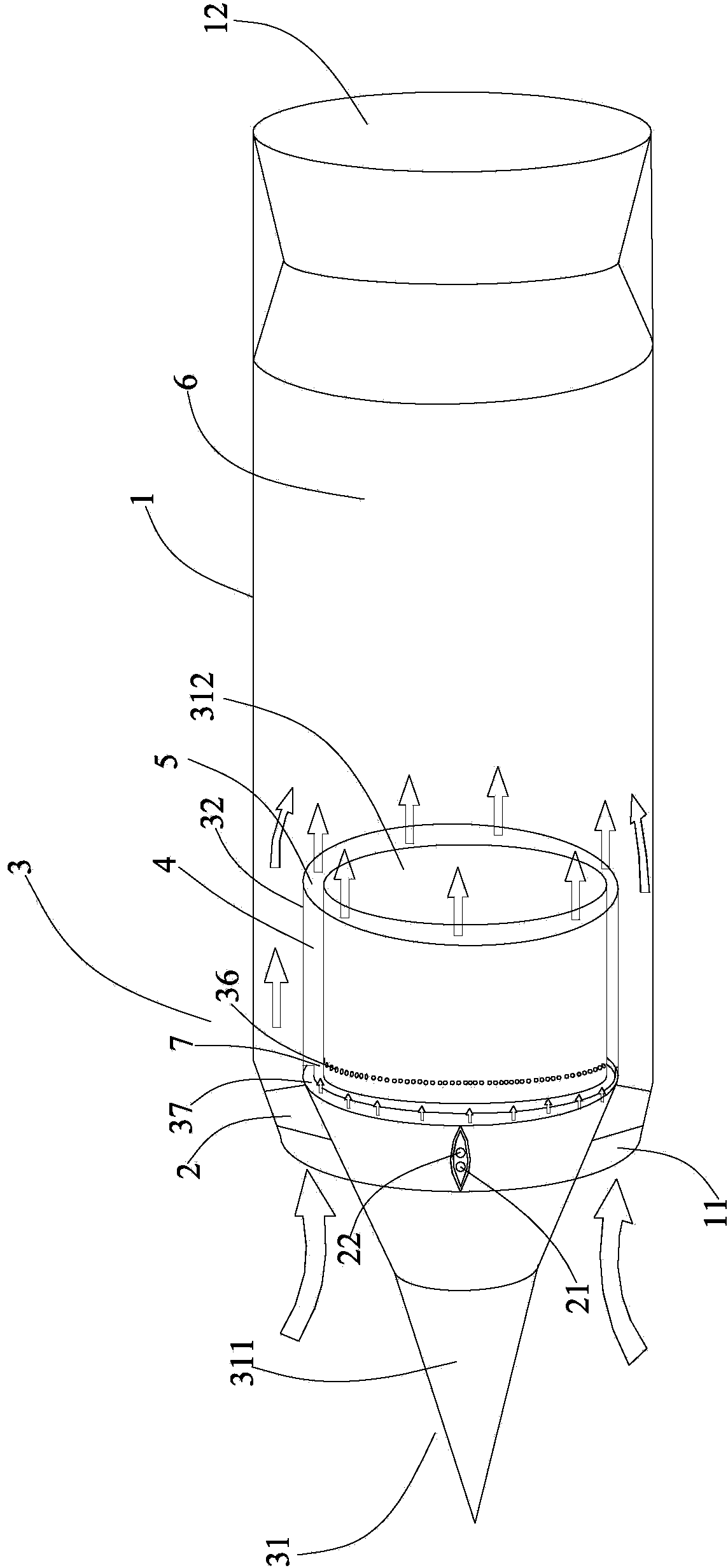
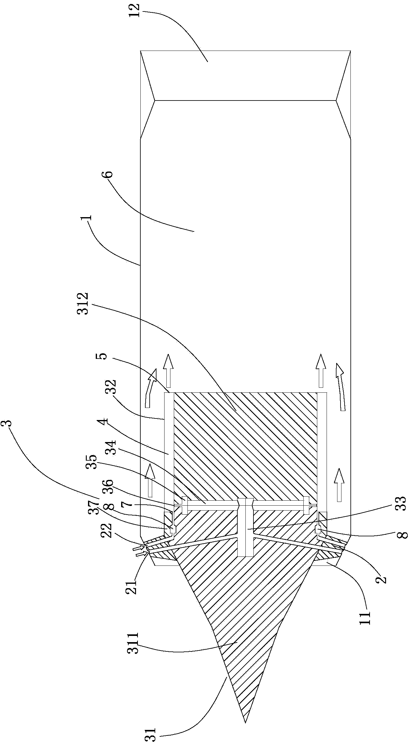
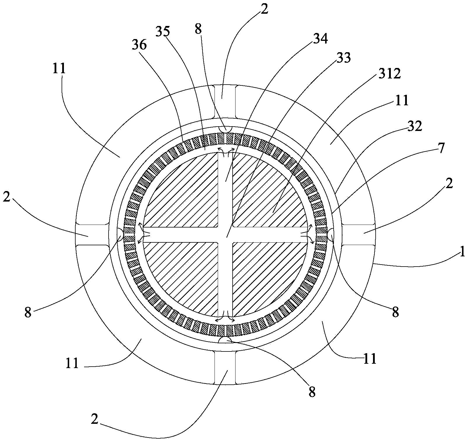
[0030] refer to Figure 1 to Figure 3 , The combined cycle engine according to the present invention includes: a casing 1; a fixed guide column 2; and a continuously rotating detonation engine 3 as an ejection device.

[0031] The casing 1 is provided with: an air inlet 11 arranged at the front end of the casing 1 , which is annular and communicates with the external atmosphere; and a supersonic nozzle 12 arranged at the rear end of the casing 1 .

[0032] The fixed guide column 2 is provided with: a fuel inlet 21, which is arranged on the outer surface of the fixed guide column 2, and communicates with an external fuel supply device (not shown); and an oxidant inlet 22, which is arranged on the outer surface of the fixed guide column 2, It is connected to an external oxidant supply (not shown).

[0033] The continuously rotatin...


PUM


Abstract

The invention provides a combined cycle engine. The combined cycle engine comprises a casing, a fixing guide column and a continuous rotation knock engine as an ejecting device. The casing is provided with an air inlet and a supersonic nozzle. The fixing guide column is provided with a fuel inlet and an oxidant inlet. The continuous rotation knock engine comprises a central conical body, a fuel collecting pipe, a plurality of fuel conveying channels, a fuel inlet pipe, a plurality of fuel nozzles and a ring-shaped body. The central conical body comprises a front body and a rear body, the casing is fixedly arranged by surrounding the outer surface of the whole rear body and part of the front body, a first combustion chamber extends axially and is defined by the casing, the outer surface of the whole rear body and part of the front body, the tail end of the first combustion chamber, which is in an axial direction, is an outlet, space between the casing and the portion behind the rear body of the central conical body inside the casing forms a second combustion chamber, the first combustion chamber is communicated with the second combustion chamber through the outlet, and the second combustion chamber is communicated with the air inlet. Therefore, the combined cycle engine can improve the ejecting efficiency of the ejecting device and simplify the structure of the ejecting device.

Description

technical field [0001] The invention relates to an engine, in particular to a combined cycle engine. Background technique [0002] In recent years, more and more concepts of combined cycle engines have emerged in front of people. Because the combined cycle engine can give full play to the respective performance advantages of various engines. In the current research on combined cycle engines in the world, the more popular combination forms are mainly rocket ramjet combined cycle engines and turbo ramjet combined cycle engines. However, in the process of actual engineering use, the turbo-ramjet combined cycle engine is subject to great development restrictions due to the complexity of its components and the strict technical requirements for the turbine engine; while the rocket ramjet combined cycle engine is relatively simple in structure, but its overall Performance cannot be improved any further. Contents of the invention [0003] In view of the problems existing in the...

Claims


Application Information

Patent Timeline
Patent Type & Authority Applications(China)
IPC IPC(8): F02K7/00
Inventor 谢峤峰王兵
Owner 清航空天(浙江)科技有限公司
Learn More