a led panel light

A technology of LED panel light and LED light source, which is applied in the field of LED lighting, can solve the problems of enlarging LED light source and diffusion plate, making it difficult to fix and locate, and increasing the difficulty of heat dissipation, so as to achieve broad application prospects, facilitate heat dissipation, and save space Effect

Inactive Publication Date: 2017-04-19
XIN FENG ELECTRICAL CO LTD
View PDF1 Cites 0 Cited by
  • Summary
  • Abstract
  • Description
  • Claims
  • Application Information

AI Technical Summary

Problems solved by technology

The direct-down panel light has the above advantages, but also has the following disadvantages: 1. The light emitted by the LED is directed down and emitted through the diffuser plate, which will inevitably cause bright spots on the lamp; to eliminate the bright spots, two Approach: a. The distance between the LED light source and the diffusion plate must be increased, which will increase the thickness of the lamp and increase the cost of the lamp shell. At the same time, the increase in thickness will increase the light transmission path and reduce the light efficiency of the lamp; b. Increase the lamp bead light source Arrangement density, increase cost, increase the power of lamps, and some occasions do not need such bright lamps
2. The problem of fixing the lamp bead, if the whole piece of aluminum substrate is used, the cost will be very high, and if the strip aluminum substrate is used, it will be difficult to fix and position
3. It is more difficult to dissipate heat, and the back plate is generally made of iron plate or 0.8mm thick aluminum substrate. Such a large-area back plate is easily deformed after installation, so that there is a gap between the light board and the back plate , the heat dissipation condition of the lamp board becomes worse, and the number of lamp beads is required too much, which leads to increased power and increased calorific value
In addition, during the production process or storage of the light guide plate, the warpage may occur, which is also a major problem restricting the use of the light guide plate.
The production methods of the light guide plate are mainly divided into two types: screen printing type and non-printing type; the screen printing type light guide plate requires less investment and does not need to invest in equipment. It can be operated manually, with low cost and high production efficiency. The technical process is very easy. However, the refraction effect of the screen-printed light guide plate is worse than that of the non-printed light guide plate; although the non-printed light guide plate has a better light refraction effect, it is expensive and difficult to master the production process, and requires professional equipment and Low production efficiency
The strength of the engraved board will be destroyed, and at the same time, the wire grooves and concave holes are easy to store dust, which brings many problems to production and application
[0011] In the prior art, a non-glare LED panel light that does not use a light guide plate, such as the application number CN201120156724.7, not only needs to increase the distance between the LED lights on both sides to increase the light-emitting area, but also needs to match the height of the cavity to achieve The effect of total reflection, however, this invention still cannot meet the requirements of large-area light output and large-area uniform light output of panel lights

Method used


Image

  • a led panel light
  • a led panel light
  • a led panel light

Examples


Embodiment 1

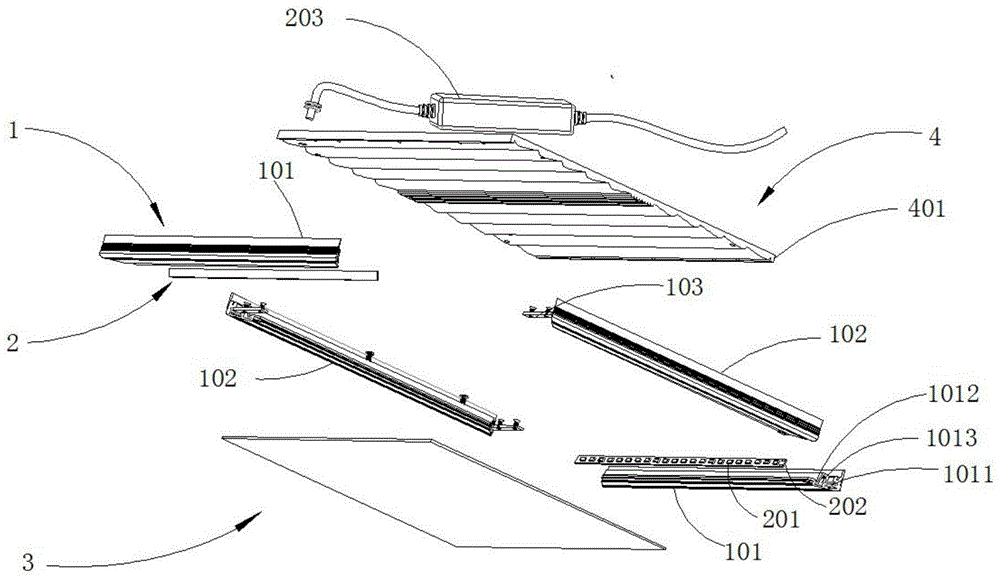
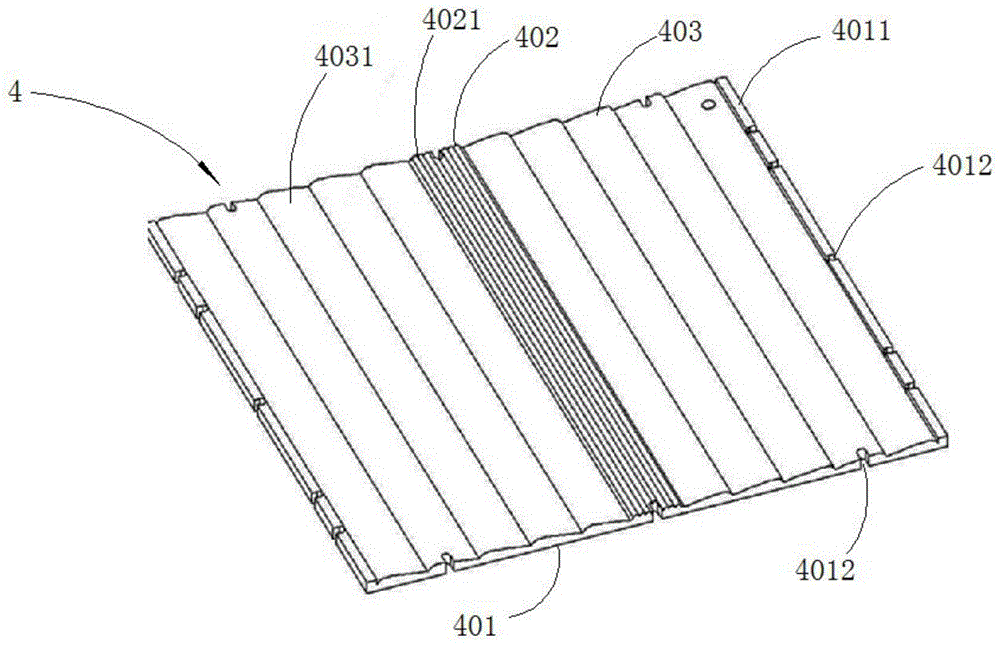
[0075] In Embodiment 1, the base plate 401 is a horizontal plate, the base plate 401 further includes two connecting plates 4011, the diffuser 402 is arranged in the middle of the base plate 401, the two connecting plates 4011 are arranged at the two ends of the base plate 401, and the two light guides 403 The diffusing part 402 and the connecting plate 4011 are respectively arranged between the two diffusing parts 402 and the connecting plate 4011 , and the two light guide parts 403 and the two connecting plates 4011 are symmetrical about the central line of the diffusing part 402 . Wherein, the connecting plate 4011 is a cuboid, and the length of the connecting plate 4011 is consistent with the lengths of the light guiding part 403 and the diffusing part 402 .

[0076] In order not to generate light spots, to make the reflective effect of the reflective plate 4 better, and to achieve the effect of uniform light output in a large area, the inventors made improvements to the LE...


PUM


Abstract

The invention discloses an LED panel light which comprises boarder sets, an LED light source, a reflection plate and a diffusion plate, wherein the boarder sets are integrated in an enclosing mode, the LED light source is arranged in the boarder sets, the reflection plate and the diffusion plate are installed in the space defined by the boarder sets, and the installation height of the reflection plate is higher than that of the diffusion plate. Compared with the prior art, the LED panel light has the advantages that the problem that according to traditional panel lights, the purposes of being free of spillage and uniform in light emission can only be realized by reducing the light-emitting area and adding materials for blocking is solved; a light guiding plate is not needed, multiple times of reflection and diffuse reflection are conducted on light through the reflection plate to enable the whole panel light to emit light uniformly through a large area, and light spots are avoided; the design is simple and clear, the structure is simple, the weight is low, the thickness is smaller than that of the traditional panel lights, and space and cost are saved; meanwhile, all the parts are installed stably, heat dissipation is facilitated, the service life of the LED light is prolonged, and therefore application prospects are quite good.

Description

technical field [0001] The invention relates to the field of LED lighting, in particular to an LED panel light. Background technique [0002] 1. Overview of LED panel lights [0003] LED panel light is a high-end indoor lighting fixture. Its outer frame is made of aluminum alloy through anodic oxidation. The light source is LED. The feeling of beauty. The LED panel light has a unique design. The light passes through the light guide plate with high light transmittance to form a uniform plane luminous effect. The uniformity of illumination is good, the light is soft, comfortable and bright, which can effectively relieve eye fatigue. LED panel lights can also prevent radiation and will not irritate the skin of pregnant women, the elderly, and children. [0004] LED panel lights are widely used, and there is a tendency to replace grille lights; LED panel lights are mainly used in: 1. Ceilings (replacing the original grille lights); 2. Walls (not only for lighting purposes, bu...

Claims


Application Information

Patent Timeline
Patent Type & Authority Patents(China)
IPC IPC(8): F21S8/00F21V7/00F21Y115/10
Inventor 何永键
Owner XIN FENG ELECTRICAL CO LTD
Why Eureka
Try Eureka