Fuel gas ignition jet tube and submerged arc furnace utilizing same

A combustion-supporting air pipe and gas technology, applied in the burner, combustion method, combustion type and other directions, can solve the problems of material freezing in the furnace, electricity consumption, longer production cycle, etc., and achieve the effect of speeding up the smelting process

Inactive Publication Date: 2014-10-22
宝鸡市晋旺达机械设备有限公司
View PDF7 Cites 3 Cited by
  • Summary
  • Abstract
  • Description
  • Claims
  • Application Information

AI Technical Summary

Problems solved by technology

In order to save energy and reduce emissions, most areas will implement peak-staggered power consumption during the peak period of power consumption. During the peak-staggered power consumption period, factories and mines can only stop production due to power outages. After the power is restored, the submerged arc furnace will be restarted for production. The temperature in the furnace will drop, causing the materials in the furnace to freeze. Reheating not only consumes electricity, but also makes the production cycle of material flow longer, and also affects the quality of smelting.

Method used


Image

  • Fuel gas ignition jet tube and submerged arc furnace utilizing same
  • Fuel gas ignition jet tube and submerged arc furnace utilizing same
  • Fuel gas ignition jet tube and submerged arc furnace utilizing same

Examples


Embodiment Construction

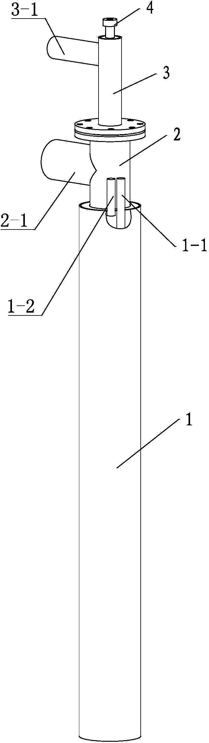
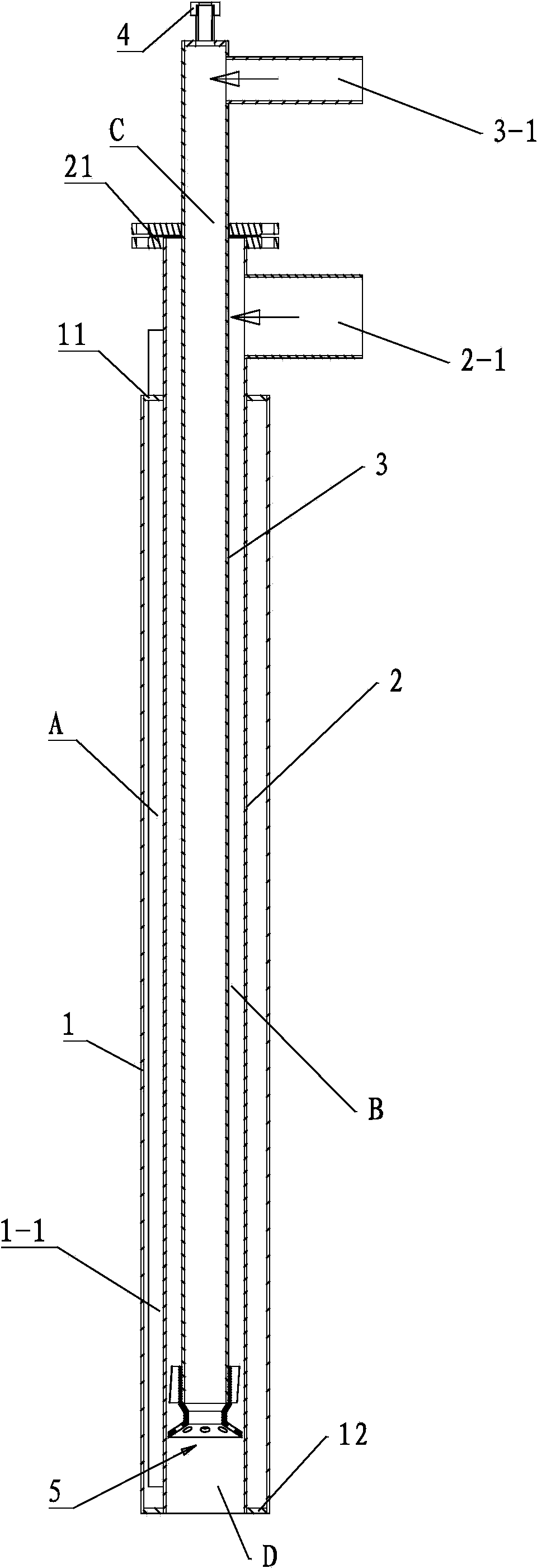
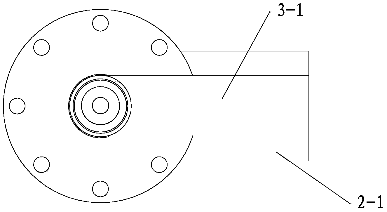
[0027] Such as Figure 1 to Figure 4 As shown, the gas ignition nozzle of this embodiment includes an outer cooling pipe 1, a middle combustion air pipe 2, and an inner gas pipe 3. The top of the outer cooling pipe 1 is provided with a top plate 11, and the bottom is provided with an annular bottom plate 12. A flange plate 21 is arranged on the top of the middle combustion air pipe 2 . Among them, the middle layer combustion air pipe 2 is arranged in the outer layer cooling pipe 1, and the upper end passes through the outer layer cooling pipe 1, the middle layer combustion air pipe 2 is connected with the air connecting pipe 2-1, and the air connecting pipe 2-1 is connected with the external air source, It is used to feed combustion air into the middle combustion air pipe 2. The inner layer gas pipe 3 is set in the middle layer combustion air pipe 2, and the upper end passes through the middle layer combustion air pipe 2, the inner layer gas pipe 3 is connected with the gas c...


PUM


Abstract

Disclosed are a fuel gas ignition jet tube and a submerged arc furnace utilizing the same. The fuel gas ignition jet tube extends into the submerged arc furnace and comprises an oxidizing air tube, a gas tube and a gas mixture nozzle, the gas tube is arranged in the oxidizing air tube, the gas mixture nozzle is arranged at the bottom of the gas tube and comprises a nozzle body and spiral airflow adjusting plates, the nozzle body comprises a converging portion and a diffusing portion, the spiral airflow adjusting plates are arranged on the outer wall of the converging portion at intervals, gas outlets are formed in the diffusing portion at intervals, the diffusing portion forms a gas outlet end face of the oxidizing air tube, an air passage is formed between the inner wall of the oxidizing air tube and the outer wall of the gas tube, an inner cavity of the gas tube serves as a gas passage, the air passage is communicated with an air connection tube, a gas passage is communicated with a gas connection tube, a gas mixing area is formed below the gas mixture nozzle, gas passes through the gas passage and then exhausted via an inner cavity of the nozzle body to the gas mixing area, and air passes through the air passage and exhausted via the gas outlets of the diffusing portion to the gas mixing area. The fuel gas ignition jet tube has the advantages that combustible gas can enter the submerged furnace, inner temperature of the submerged furnace can be kept, and energy conservation and emission reduction are realized.

Description

technical field [0001] The invention belongs to the technical field of metallurgical equipment, and in particular relates to a submerged arc furnace and a gas ignition nozzle used in the submerged arc furnace. to get high energy. Background technique [0002] The submerged arc furnace is an electric furnace that uses the high-temperature smelting ore or metal generated by the electrode arc. It is mainly used for ore smelting. Its furnace body structure is similar to that of the steelmaking electric arc furnace. The arc between the electrode and the charge will generate heat. When the current passes through the charge, the resistance of the charge will also generate considerable heat. The submerged arc furnace uses the energy of the arc and the heat of the current passing through the charge to smelt metal or non-metallic ores. [0003] During the smelting process of the submerged arc furnace, the ore in the furnace is smelted through the arc striking of the electrode, which...

Claims


Application Information

Patent Timeline
Patent Type & Authority Applications(China)
IPC IPC(8): F23D14/02F27B3/20
Inventor 关兴旺关珍旺关越张国庆郭云奇
Owner 宝鸡市晋旺达机械设备有限公司
Why Eureka
Try Eureka