Induction cooker with magnetic stripe arranged at upper side of support

A technology on an induction cooker and a bracket, applied in the field of induction cookers, can solve the problem of the induction cooker being not thin enough, and achieve the effects of being favorable for heat dissipation, easy to form, and easy to damage

Active Publication Date: 2014-10-22
JOYOUNG CO LTD
View PDF6 Cites 4 Cited by
  • Summary
  • Abstract
  • Description
  • Claims
  • Application Information

AI Technical Summary

Problems solved by technology

[0004] In order to solve the above problems, the present invention provides an induction cooker with a magnet...

Method used


Image

  • Induction cooker with magnetic stripe arranged at upper side of support
  • Induction cooker with magnetic stripe arranged at upper side of support
  • Induction cooker with magnetic stripe arranged at upper side of support

Examples


Embodiment 1

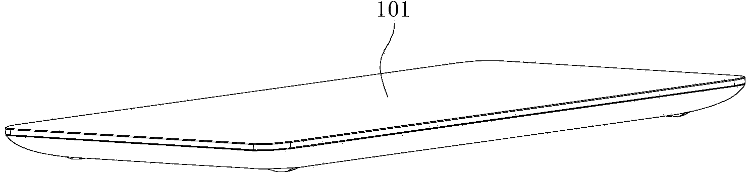
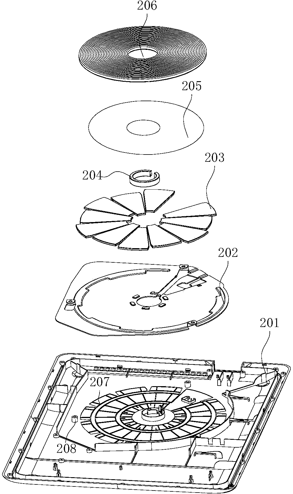
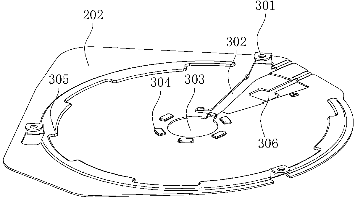
[0028] refer to figure 1 , figure 2 , image 3 , Figure 4 and Figure 5 , an induction cooker 101, comprising a panel and a bottom case 201, the panel and the bottom case 201 enclosing a cavity, the cavity contains a bracket 202, a magnetic strip, a coil 206, etc., wherein the bracket 202 is made of aluminum and is plate-shaped and directly It is fixed on the bottom shell 201 . A plurality of fan-shaped magnetic strips 203 and a ring-shaped magnetic strip 204 are arranged on the bracket 202 , the plurality of fan-shaped magnetic strips 203 enclose a magnetic ring, an insulating sheet 205 is arranged on the magnetic ring, and a coil disk 206 is arranged on the insulating sheet 205 . Wherein the insulating sheet 205 can adopt insulating materials such as mica sheet and plastic sheet. Wherein, the bracket 201 can also be made of copper material.

[0029] refer to Figure 4 The above-mentioned magnetic strip is bonded to the bracket 202, the insulating sheet 205 is bonded...

Embodiment 2

[0038] refer to Figure 6 , based on the structure in Embodiment 1, the center of the bottom shell 201 is provided with an accommodating groove 604 for accommodating a temperature sensor for measuring the temperature of the panel. The outer side of the accommodation groove 604 is provided with a plurality of limiting pieces 603, the plurality of limiting pieces 603 form a third ring, the edge of the first through hole in the center of the bracket 202 extends upwards to form a plurality of third protrusions 602, and the plurality of third protrusions 602 are formed. Protrusions 602 form a fourth ring. After the induction cooker 101 is installed, the third ring and the fourth ring fix the annular magnetic strip 204 .

[0039]The screw holes 301 on the edge of the bracket 202 are provided on the beam 601 , and the beam is more stable during the screwing process, which facilitates fixing the bracket 202 on the bottom case 201 .

Embodiment 3

[0041] Based on the structure in Embodiment 1, the bracket 202 is directly arranged on the bottom case 201, and there is no gap between the lower surface of the bracket and the inner surface of the bottom case 201, so that the induction cooker can be made thinner.


PUM

PropertyMeasurementUnit
Thicknessaaaaaaaaaa
Thicknessaaaaaaaaaa

Abstract

The invention relates to the field of household electrical appliance and especially relates to an induction cooker (101) with a magnetic stripe arranged at the upper side of a support. The induction cooker comprises a panel and a bottom casing (201), the panel and the bottom casing (201) form a cavity, a support (202), the magnetic stripe and a coil (206) are arranged in the cavity, and the support (202) is prepared from Al, is in a shape of a plate and is directly and fixedly arranged on the bottom casing (201). The coil (206), the magnetic stripe, an insulation sheet (205) and the support (202) are fixed to form a heating module by bonding connection or clamp connection. The induction cooker has an ultrathin structure having the thickness less than 20mm, has unaffected thermal diffusivity and avoids reverse direction heating problems.

Description

technical field [0001] The invention relates to the field of household appliances, in particular to an induction cooker with a magnetic strip arranged on the upper side of a bracket. Background technique [0002] With the development of urbanization in China, more and more people are moving from rural areas to cities. However, due to the lack of houses and the large number of people, the living environment of most people is relatively small. And this situation is difficult to disappear with the development of economy and technology. In this case, the volume of indoor electrical appliances should be designed as small as possible. If it is an electrical appliance that is placed where the human eye can see it, it should be designed as beautifully as possible. [0003] As an electrical appliance widely used in Chinese households, induction cooker is gradually developing in the direction of ultra-thin. However, the thinner the induction cooker is, especially when it develops b...

Claims


Application Information

Patent Timeline
IPC IPC(8): F24C7/06
Inventor 朱泽春王涛管兴勇
Owner JOYOUNG CO LTD
Why Eureka
Try Eureka